3 connecting the power cables, 1 connecting the power cables in the left system – SMA SC 630HE-11 User Manual
Page 4
SMA Solar Technology AG
Mounting and internal cabling
Installation Guide
4/5
SC_Chem_Aktiv-IEN092911
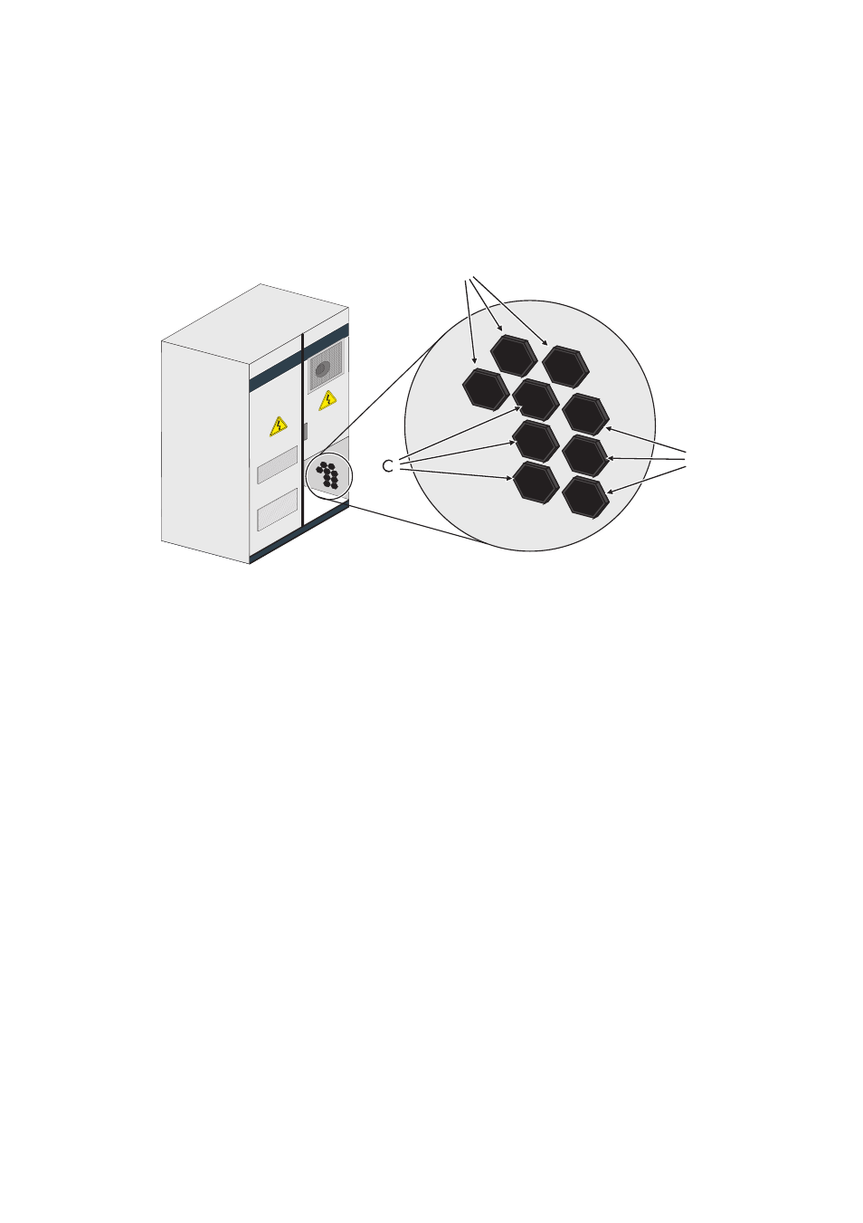
3.3 Connecting the power cables
The power cables are included in the delivery and must be connected to the power units in the inverter
cabinet and to the sine filter choke in the AC cabinet. 3 cables are connected per phase. The cable
routing in the right and left system is different. The following illustration shows the position of the glands
in the left system, the position of the glands in the right system are mirror-inverted.
3.3.1 Connecting the power cables in the left system
1. Connect L3 at the lower power unit in the inverter cabinet.
2. Insert L3 through the cable gland A.
3. Connect L3 at the sine filter in the AC cabinet according to the label.
4. Tighten the cable gland A.
5. Connect L1 at the middle power unit in the inverter cabinet.
6. Insert L1 through the cable gland B.
7. Connect L1 at the sine filter in the AC cabinet according to the label.
8. Tighten the cable gland B.
9. Connect L2 at the upper power unit in the inverter cabinet.
10. Insert L2 through the cable gland C.
11. Connect L2 at the sine filter in the AC cabinet according to the label.
12. Tighten the cable gland C.
A
B