SMA RS485-Quick Module V.3.0 User Manual
Contact, Technical data, Scope of delivery safety
ContaCt
EN
Accessories for SUNNY BOY 2000HF/2500HF/3000HF
RS485-Quick Module
Installation Guide
485Q-Module-IEN111830 | IMEN-485QMODULE | Version 3.0
If you have technical problems concerning our products, contact the SMA Serviceline. We
require the following information in order to provide you with the necessary assistance:
• Serial number of the RS485-Quick Module
• Inverter type
• Inverter serial number
• Type and number of PV modules connected
• Event number or display of the inverter
• Type of communication, if applicable
SMa Solar technology aG
Sonnenallee 1
34266 Niestetal, Germany
www.SMA.de
SMa Serviceline
Inverters:
+49 561 9522 1499
Communication: +49 561 9522 2499
Fax:
+49 561 9522 4699
E-Mail:
Check the delivery for completeness and for any visible external damage. Contact your dealer
if anything is damaged or missing.
RS485-Quick Module
Installation guide
RS485 cabling plan poster
appropriate Usage
The RS485-Quick Module is provided as an upgrade kit or included in the scope of delivery of
the inverter.
The RS485-Quick Module is only suitable for use with SMA inverter of type Sunny Boy
2000HF/2500HF/3000HF. Please also observe the installation guide of the respective inverter.
The RS485-Quick Module is equipped with an RS485 interface and a multi-function relay. Via
the RS485 interface, you can establish a wired RS485 communication of the above mentioned
SMA inverter types.
The multi-function relay serves to connect or disconnect a fault indicator or external load,
depending on the power availability of the inverter. For the description of the functions of the
multi-function relay (as of firmware version 2.10) please refer to the Technical Description
“Multifunction Relay and OptiTrac Global Peak” at the download area www.SMA.de/en.
Safety Precautions
DanGER!
Electric shock caused by high voltages in the inverter.
• All work on the inverter may be carried out by qualified personnel only.
• Disconnect the inverter from both the DC and AC side, as described in the
inverter's installation guide.
notICE!
Electrostatic discharges can damage the RS485-Quick Module or the
inverter.
• Ground yourself before touching the component by touching PE or a grounded
object.
Cable length
You have to make sure that the cables are long enough for connecting the RS485-
Quick Module to the inverter. After connecting them, remember that the RS485-Quick
Module has to be pushed approx. 10 cm in the inverter (see "Mounting the Device").
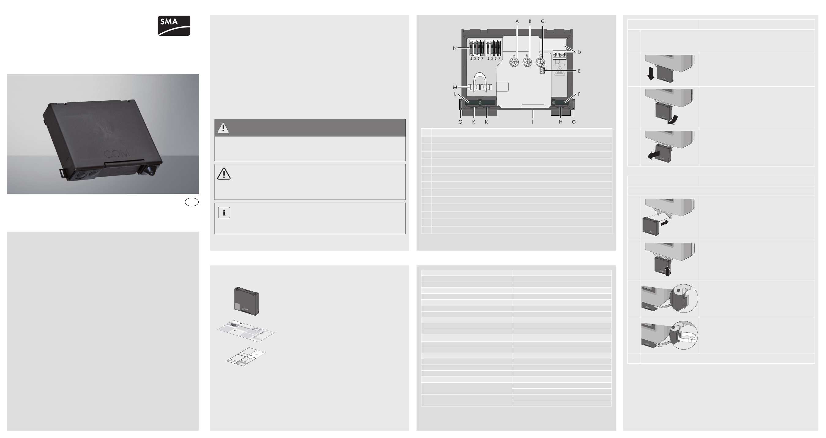
Description
A Rotary switch for setting the installation country (switch A)
B
Rotary switch for setting the display language (switch B)
C Rotary switch for the configuration of Bluetooth communication (switch C)
D Multi-function relay and connection terminal
E
Jumper slot for temporarily setting the language to English, e. g. during servicing (E)
F
Strain relief
G Securing eyelets with cable ties
H Enclosure opening for connecting the multi-function relay
I
Slot for SD card
K Cable support sleeve with filler plugs for connecting the RS485 bus
L
Strain relief
M Shield clamps with 2 self-adhesive cooper foil strips
N two 4-pole spring-type terminals for connecting the RS485 bus to a termination resistor
PRoDUCt ovERvIEw
REPlaCEMEnt of thE RS485-QUICk MoDUlE
Interfaces
Field bus
2 x 4 spring-type terminals
Multi-function relay
3-pole screw terminal
Communication
Communication interfaces
RS485, Bluetooth
Maximum communication range
RS485
1,200 m
Bluetooth in the open air
100 m
Environmental conditions in operation
Ambient temperature
–25 °C … +60 °C
Relative humidity (non condensing)
5 % … 95 %
ambient conditions during storage
Ambient temperature
–40 °C … +85 °C
Relative air humidity
5 % … 95 %
General data
Width x height x depth
124 mm x 97.5 mm x 27 mm
Weight
180 g
Installation location
in the inverter
Multi-function relay data
Voltage
AC: max. 240 V
DC: max. 30 V
Current
AC: max. 1.0 A
DC: max. 1.0 A
tEChnICal Data
Disassembly
1. Disconnect the inverter from both the DC and AC side, as described in the inverter's
installation guide. If a multi-function relay is connected, switch off the multi-function
relay power supply.
2.
Pull the integrated Quick Module out to the first
stopper.
3.
Press the Quick Module lightly forwards until the keys
pass through the openings of the bracket.
4.
Carefully take the Quick Module out of the bracket.
Mounting
Install the RS485-Quick Module carefully in the inverter.
1.
Put the RS485-Quick Module into the designated holes
on the bracket.
2.
Push the RS485-Quick Module upwards in the guide
slot until it clicks into place.
3.
Check that the RS485-Quick Module is securely in
place. The loops of the RS485-Quick Module and the
bracket must be positioned flush on top of each other.
4.
Mechanical fuse:
You can fix the RS485-Quick Module with cable ties
to prevent someone that someone accidentally takes it
out. There are two loops on top of each other. Guide
the cable ties through these loops and tighten them.
☑ The RS485-Quick Module is mounted.
SCoPE of DElIvERy
SafEty