3 operating modes, Operating modes – SMA SB 2000HF-US User Manual
Page 13
SMA America, LLC
Operating Modes
User Manual
HF_STP_US-BUS095110
13
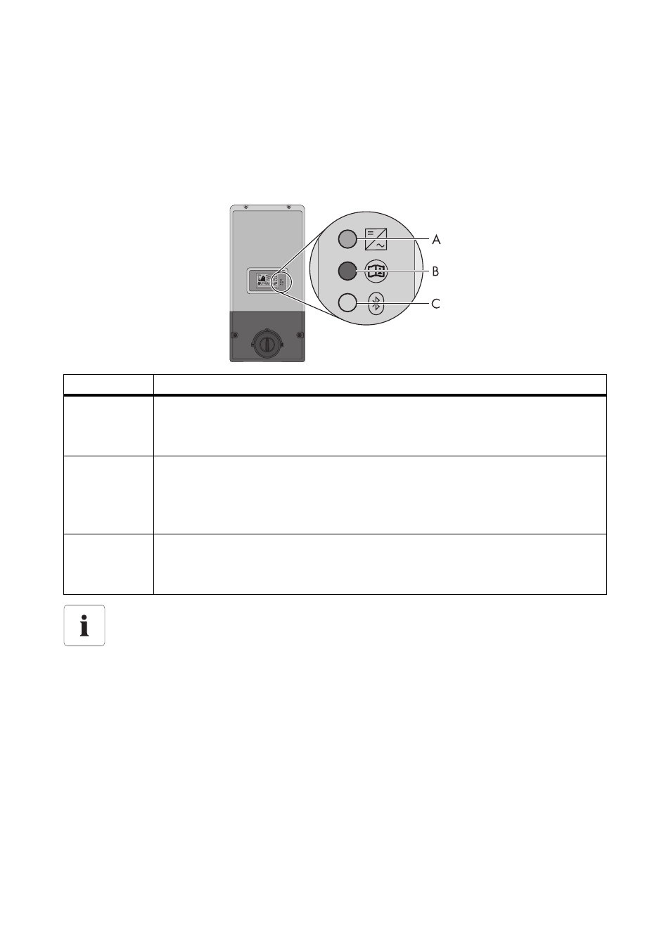
3 Operating Modes
The inverter indicates various operating conditions with the help of 3 LEDs on the enclosure lid. The
equipment must be connected to a DC power supply. Furthermore the equipment must be connected
to the grid on the AC side to be able to indicate its operational state via display and integrated LEDs.
There must be adequate solar radiation for the inverter to receive the necessary DC voltage.
The following section contains a detailed description of various LED displays and inverter operating
states.
LED
Description
A
Green LED
LED lit: Inverter in normal operating mode
LED flashing: Inverter waiting for adequate solar radiation
B
Red LED
LED lit: Fault in the inverter. Note the serial number of the inverter and the fault
number and contact your installer. The fault number is indicated on the inverter
display unit.
C
Blue LED
LED lit: Inverter is connected to a Bluetooth network and can communicate with
other devices having the same NetID.
LED display
In case you do not have any communication devices available, monitor the LEDs of the
inverter and graphic display regularly at various times during the day and under varying
conditions of solar radiation, particularly in the first year after installation. Thus, you can
detect any potential faults in the system in a timely manner.