Led modes safety precautions product overview, Display status messages measuring channels – SMA SB 1200 User Manual
Page 2
DANGEr!
Electric shock caused by high voltage in the inverter.
Even when no external voltage is present, there can still be high voltages in the device.
The following work may be carried out by qualified personnel only:
• Electrical installation
• Repairs
• Modification
CAUTION!
risk of injury from touching the enclosure during operation.
Burns to the body.
• Only touch lid and display during operation.
NOTICE!
Overvoltage in the inverter if yellow LED flashes 4 times.
Destruction of the inverter.
• Inform your installer immediately if the yellow LED starts
flashing and the following display message appears.
Operation
The display shows current values of your system. The displayed values
are updated every 5 seconds. The display is operated by tapping on it.
Tap once: The backlight is switched on. After 2 minutes, the illumination
switches off automatically.
Tapping once more:The display switches to the next notification.
Tapping twice: The display successively shows inverter type, firmware
version of the internal processors and configured country standard.
Display messages
Operation
Upon error-free connection of the inverter to the grid, the following
messages are shown in turn after approximately 1 minute. Each
message appears for 5 seconds, then the cycle starts again.
Power produced on the current day
Operating state
Current feed-in power
PV generator voltage
Total amount of feeding-in energy
Total number of grid-feeding operational hours
Disturbance
In the event of a disturbance, the inverter will display the status
"Disturbance" and an error message. Please inform your installer.
The following messages will be issued:
Power produced on the current day
Operating state "Disturbance"
Operating state
Error message
Measured value at time of disturbance
Current measured value (only displayed if a measured value is
responsible for the disturbance)
DC overvoltage
The DC input voltage connected to the inverter is too high.
Please inform your installer immediately.
State
Description
function
All LEDs are
on
Initialization
The inverter is initializing.
All LEDs are
off
Deactivation
The inverter has detected a DC input voltage that is
too low for grid feeding.
Green
LED is
permanently
on
Feeding
Operation
The inverter is feeding power into the public grid.
Green LED
is flashing
Waiting, Grid
Monitoring
The inverter monitors the grid and waits for the DC
voltage to reach a certain level so that it can start
feeding the grid.
Stop
Interruption of operation.
Derating
Overtemperature in the inverter.
Red LED is
glowing
Warning
A grounding error has occurred, or one of the
thermally monitored varistors on the DC input side is
defective. Please inform your installer.
Yellow LED
is glowing
continuously
Disturbance
The inverter is operating in "Operation constantly
disabled" mode. This can have several causes.
Please inform your installer.
Yellow LED
is flashing
Disturbance
The inverter displays a disturbance. This can have
several causes. Please inform your installer.
If your inverter is equipped with a communication component, then numerous measuring channels
and messages can be transmitted for diagnosis.
Measuring channel
Description
Error
Identification of the current disturbance / error.
E-total
Total amount of feeding-in energy
Event-Cnt
Number of events that have occurred
Fac
Grid frequency
h-On
Total number of operating hours
h-total
Total number of grid-feeding operational hours
Iac
Grid current
Ipv
DC current
Mode
Display of the current operating mode
Pac
Generated AC power
Power On
Total number of grid switch-ons
Riso
Insulation resistance of the PV system to the power supply line
Serial number
Inverter serial number
Vac
Grid voltage
Vpv
PV input voltage
Vpv-Setpoint
PV target voltage
Your inverter can be in various operating modes. These are displayed as status messages, which can
vary according to the method of communication.
Message
Description
Derating
Overtemperature in the inverter. The inverter will reduce its output to prevent
overheating. To avoid unnecessary output losses, the design of the PV plant
should be checked. Please inform your installer.
Disturbance
Disturbance. This message appears for reasons of safety and prevents the
inverter from connecting to the grid. Please inform your installer.
Error
An error has been detected. Please inform your installer.
grid mon.
Grid monitoring
This message appears during the startup phase, before the inverter connects to
the grid; it usually appears in the morning and evening when there is little solar
irradiation an after an error has occurred.
MPP
The inverter is operating in MPP mode. MPP is the standard display message
when operating under normal irradiation conditions.
Off Grid
The inverter is in "Island" mode. This mode has been specially conceived for
operation in an off-grid power system with a Sunny Island as grid controller.
offset
Offset adjustment of measurement electronics.
Riso
Measurement of the insulation resistance of the PV system.
Stop
Interruption of operation.
V-Const
Constant voltage operation.
waiting
The switch-on conditions are not (yet) fulfilled.
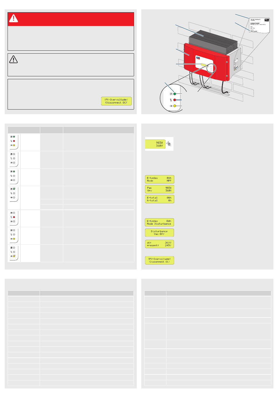
LED MODES
SAfETY PrECAUTIONS
PrODUCT OVErVIEw
Cooling fins
Enclosure lid
Display
LEDs
Serial number
Identification of the Sunny Boy by the type label
Operation
Ground fault or varistor defective
Disturbance
DISPLAY
STATUS MESSAGES
MEASUrING ChANNELS