Checking the connections via the display, 6 configuring the cluster controller, 7 contact – SMA CLUSTER CONTROLLER Quick Reference Guide User Manual
Page 2: 6 configuring the cluster controller 7 contact
7
8
5
6
Connecting the Cluster Controller to the Voltage Supply
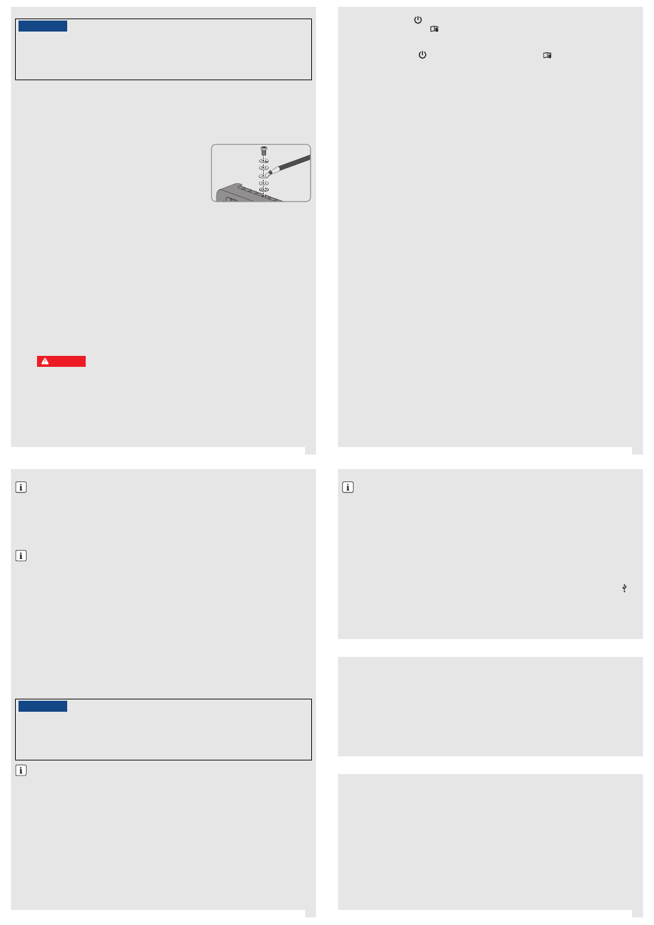
Connecting the Grounding Conductor to the Cluster Controller
Additionally required material (not included in the scope of delivery):
☐ 1 grounding conductor (see Section Cable Requirements)
Procedure:
1. Remove 10 mm (0.39 in) of the cable sheath from the grounding conductor.
2. Insert the insulated conductors into the ring terminal lug and crimp with a crimping tool.
3. Attach the grounding conductor at the terminal for grounding
(for the position of the terminal, see installation manual on the CD
included in scope of delivery). Observe the following sequence
and hand-tighten the fastening screws (torque: 0.8 Nm
(7.08 in-lb)):
– Fastening screw, split lock washer, washer, ring terminal lug
with grounding conductor, washer, tooth lock washer
Connecting the Power Supply Unit
Additionally required material (not included in the scope of delivery):
☐ 1 power supply unit (available as an accessory). If the power supply unit available as an accessory is not
used, observe the requirements for the power supply unit (see installation manual on the CD included in the
scope of delivery).
☐ 1 AC connection cable
☐ 1 connection cable for the connection of the power supply unit to the Cluster Controller (see Section Cable
Requirements).
Procedure:
1. Mount the power supply unit (see the manufacturer manual).
2. Connect the connection cable to the power supply unit (see the manufacturer manual). Trim the unused
insulated conductors up to the cable sheath and note down the conductor colors.
3. Connect the connection cable to the three-pole plug. Release conductor entries 2 and 3 with a screwdriver
and insert the insulated conductors into the conductor entries. Observe the pin assignment.
4. Connect the three-pole plug to terminal X1 of the Cluster Controller.
5. Connect the AC connection cable to the power supply unit (see the manufacturer manual).
7. Connect the other end of the AC connection cable to the voltage supply.
/05*$&
Damage to the Cluster Controller due to condensation water
If the Cluster Controller is moved from a cold environment to a warm environment, condensation water may
form in the Cluster Controller.
• In the event of large temperature differences, only supply voltage to the Cluster Controller once the
Cluster Controller has reached room temperature.
6.
%"/(&3
Danger to life due to electric shock
Lethal voltages are present at the connection point of the utility grid.
• Disconnect the connection point from voltage sources and ensure that the connection point is
voltage-free.
8. Connect the connection point to the utility grid.
☑ The power LED (
) of the Cluster Controller glows red for two seconds, then it permanently glows
green. The status LED (
) glows corresponding to the current device status (see Cluster Controller
installation manual on the CD included in the scope of delivery). The Cluster Controller is ready for
operation after a maximum of one minute.
✖ Is the power LED (
) glowing permanently red, the status LED (
) glowing yellow or red and the
Cluster Controller is not starting?
Possible fault cause: the voltage supply is too low.
• Ensure that the connected voltage supply is sufficient (for requirements for the voltage supply see
the installation manual on the CD provided). If the problem persists, contact the SMA Service Line
(see Section 7).
Checking and Setting the System Time of the Cluster Controller
Before connecting the Cluster Controller to the Speedwire network and before commissioning the inverters, you
must use the display of the Cluster Controller to check whether the correct system time is displayed on the Cluster
Controller. If the correct system time is not displayed, you must set the correct system time via the user interface of
the Cluster Controller. This avoids inconsistencies in the time settings of the inverters.
Requirement:
☐ The Cluster Controller must be connected to the voltage supply and be in operation (see Section
Connecting the Cluster Controller to the Voltage Supply).
Procedure:
1. Use one network cable to connect the computer to the network port X13 or X14 of the Cluster Controller.
2. Log into the Cluster Controller:
• Select the display view External communication and read off the IP address of the Cluster Controller.
• Enter the IP address in the address bar of the web browser.
• Log in with the default system password (User = "0000", Installer = "1111").
3. Select the Cluster Controller in the system tree and select the Settings menu in the device menu.
4. Select the Device > Time settings parameter group.
5. Select [Edit].
6. If required, use the Standard/Daylight Saving Time conversion on drop-down list to set automatic
conversion between standard and daylight saving time.
7. In the Set PV system time field, set the current date and time of the PV system.
8. In the drop-down list Time zone, select the time zone in which the system is located.
9. Select [Save].
☑ The PV system time is updated.
10. Select [Logout] in the toolbar.
11. Connect the Cluster Controller to the Speedwire network (see Section Connecting the Cluster Controller
to a Speedwire Network) and make any additional required connections.
Connecting the Cluster Controller to a Speedwire Network
Requirements:
☐ The nodes in the Speedwire network (e. g. inverters) must be cabled in accordance with one of the possible
network topologies (see the node installation manual and the Technical Information "SMA Speedwire
Fieldbus").
Additionally required material (not included in the scope of delivery):
☐ Depending on the network topology: network cable (see Section Cable Requirements).
Procedure:
• Connect the network cable to the network port X9 or X10 of the Cluster Controller.
Connecting the Cluster Controller to the Local Area Network
Additionally required material (not included in the scope of delivery):
☐ 1 network cable (see Section Cable Requirements)
Procedure:
1. Connect the network cable to the network port X13 or X14 of the Cluster Controller.
2. Connect the other end of the patch cable to the desired device in the local area network (LAN).
Do not connect the Speedwire network and the local area network (LAN)
The Speedwire network is a separate network managed by the Cluster Controller. If the Speedwire
network and the local area network (LAN) are connected, a disturbance of both networks is likely to
occur.
• In order to ensure correct communication, do not connect the Speedwire network and the local
area network (LAN). The Speedwire bus and the Ethernet bus must not be connected to the same
switch.
Observe the configuration of the router and the network switch
For the Speedwire connection, the Cluster Controller uses IP addresses from the Unicast area and also
IP addresses from the Multicast area 239/8 (239.0.0.0 to 239.255.255.255).
• When using a router or network switch, ensure that the router and switch forward the Multicast
telegrams required for the Speedwire connection to all nodes of the Speedwire network
(for information on configuration of the router or switch, see the manufacturer manual).
/05*$&
High costs possible through inappropriate Internet rates
Depending on use, the data volume of the Cluster Controller transferred via the Internet can be more than 1
GB per month. The data volume depends, among other things, on the number of inverters, the frequency of
device updates, the frequency of data transfer to the Sunny Portal and the use of FTP push.
• SMA recommends using an Internet flat rate.
Different IP address ranges required for Speedwire network and local network (LAN)
In order to clearly assign the IP addresses in the Speedwire network and in the local network (LAN) from
the perspective of the Cluster Controller to be possible, the IP address ranges of both networks must be
different. By default, the Cluster Controller uses address range 172.22/16 (172.22.0.1 to
172.22.255.255) for the Speedwire network.
• Make sure that different IP address ranges are used for the Speedwire network and the local
network (LAN).
Connecting USB Data Carriers to the Cluster Controller
Additionally required material (not included in the scope of delivery):
☐ Up to two USB data carriers, e.g. two USB sticks (available as an accessory). If the USB data carrier available as
an accessory is not used, observe the requirements for USB data carriers (see installation manual on the CD
included in the scope of delivery).
Procedure:
1. Connect the USB data carrier to the desired USB terminal of the Cluster Controller.
• To export system data, connect the USB data carrier to the USB terminal 1.
• To transmit update files to the Cluster Controller, connect the USB data carrier to USB terminal 2.
2. If the USB data carrier is to be removed from the Cluster Controller, wait until the data carrier status LED (
) is
not flashing anymore.
Checking the Connections via the Display
• You can use the display of the Cluster Controller to check whether the connections have been made correctly and
whether all inverters, sensors and remote terminals have been recorded by the
Cluster Controller (see installation manual on the CD included in the scope of delivery).
Requirement:
☐ The Cluster Controller and the computer must be located in the same local area network (LAN).
Procedure:
1. Log
into the Cluster Controller:
• Select the External Communication display view and read out the IP address of the Cluster Controller.
• Enter the IP address in the address bar of the web browser.
• Log in with the default system password (User = "0000", Installer = "1111").
2. Deactivate the Webconnect function of the inverters (see user manual of the Cluster Controller on the CD included
in the scope of delivery).
3. Make further desired configurations via the user interface (see user manual on the CD included in the scope of
delivery).
If you have technical probl
ems with our products, contact the SMA Service Line. We require the following information
in order to provide you with the necessary assistance:
• Serial number and firmware version of the Cluster Controller
• Type, serial number, and firmware version of the inverter
• When using a retrofitted Speedwire/Webconnect interface:
Serial number and firmware
version of the Speedwire/Webconnect interface
Not possible to use USB hubs
The Cluster Controller does not support any USB hubs. You must connect the USB data carrier directly
to the desired USB terminal on the Cluster Controller.
6 CONFIGURING THE CLUSTER CONTROLLER
7 CONTACT
SMA Solar Technology AG
Niestetal, Germany
International SMA Service Line
Toll free worldwide: 00800 SMA SERVICE
(+800 762 7378423)
SMA America, LLC
Rocklin, CA, United States/Estados Unidos
+1 877-MY-SMATech (+1 877-697-6283)*
+1 916 625-0870**
SMA Canada, Inc.
Toronto, Canada/Canadá
+1 877-MY-SMATech (+1 877-697-6283)***
* toll free for USA, Canada and Puerto Rico / Llamada gratuita en EE. UU., Canadá y Puerto Rico
** international / internacional
*** toll free for Canada / gratuit pour le Canada