SMA CLUSTER CONTROLLER Quick Reference Guide User Manual
1 information on this document 2 safety, 3 scope of delivery 4 mounting, 5 connection and commissioning
ClusterController-IS-en-12 | Version 1.2
ENGLISH
2
3
4
at
Validity
This document is valid for the SMA Cluster Controller (model: CLCON-10 and CLCON-S-10
)
from hardware
version A1 and from firmware version 1.0.
Target Group
This document is intended for qualified persons. Only persons with the following skills are allowed to perform the
tasks set forth in this document:
• Training in the installation and commissioning of electrical devices
• Training in how to deal with the dangers and risks associated with installing and using electrical devices and
systems
• Training in the installation and configuration of IT systems
• Knowledge of how an inverter works and is operated
• Knowledge of all applicable standards and directives
• Knowledge of and compliance with this document and all safety precautions
Intended Use
The Cluster Controller* is a device for monitoring and controlling SMA inverters with Speedwire/Webconnect interface
in decentralized PV systems and large-scale PV power plants. The Cluster Controller is an ITE class A device as per
EN 55022 and is designed for industrial use. The Cluster Controller must only be used in an indoor environment and
must only be used with supported products (for a list of the supported products, see the installation manual on the CD
included in the scope of delivery). Use this product only in accordance with the information provided in the enclosed
documentation and with the locally applicable standards and directives. Any other application may cause personal
injury or property damage.
For safety reasons, it is not permitted to modify the product or install components that are not explicitly recommended or
distributed by SMA** for the product. Unauthorized modifications and installations will void all warranty claims and the
operating permission. Any use of the product other than described in the Intended Use section does not qualify as
appropriate.
The type label must remain permanently attached to the product.
The enclosed documentation is an integral part of this product. Before installing or using the product, read and
observe all instructions, safety precautions and warning messages in this document and in the product
documentation on the enclosed CD.
Safety Precautions
1 INFORMATION ON THIS DOCUMENT
2 SAFETY
* In this document, the SMA Cluster Controller is referred to as Cluster Controller.
** SMA = SMA Solar Technology AG, SMA America LLC, SMA Solar Technology Canada Inc.
%"/(&3
Danger to life due to electric shock
If overvoltage occurs (e. g. due to lightning) or if the enclosure of the Cluster Controller is not grounded, there
is a danger of electric shock.
• Ensure that the Cluster Controller is integrated in the existing lightning protection.
• Ground the enclosure of the Cluster Controller (see Section Connecting the Grounding Conductor
to the Cluster Controller).
/05*$&
Damage to the devices and cables
The Cluster Controller is not splash water-protected (degree of protection: IP20 (NEMA 1)). Consequently, it
is possible that moisture may penetrate the device.
• Only use the Cluster Controller in a dry, indoor environment.
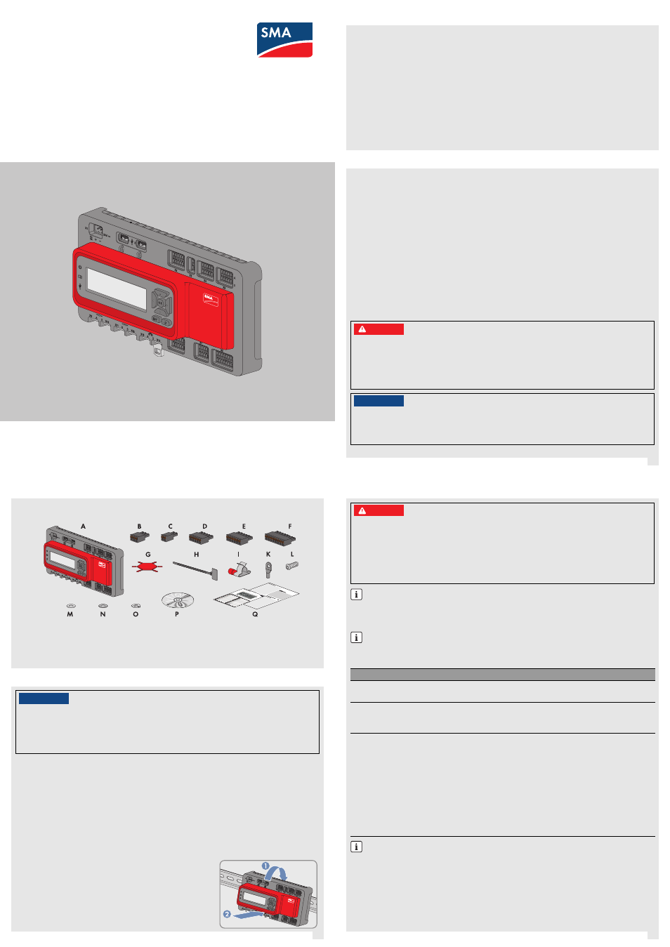
Check the scope of delivery for completeness and any externally visible damage. Contact your distributor if the
scope of delivery is incomplete or damaged.
A) 1 x Cluster Controller, B) 1 x three-pole plug, C) 1 x two-pole plug, D) 2 x five-pole plug, E) 8 x six-pole plug,
F) 2 x eight-pole plug, G) 2 x coding element, H) 20 x cable tie with writing field, I) 8 x shield clamp with ring
terminal lug, K) 1 x ring terminal lug, L) 1 x fastening screw, M) 2 x washer, N) 1 x tooth lock washer,
O) 1 x split lock washer, P) 1 x CD with product documentation, Q) 1 x quick reference guide for commissioning
and supplementary sheet for writing down the connected devices
Selecting the Mounting Location
Select the mounting location. Observe the mounting location requirements, the minimum clearances and the
permissible mounting position (see installation manual on the CD provided).
Mounting the Cluster Controller
Requirements:
☐ A 35 mm (1.4 in) wide top-hat rail must be available which is mounted securely on the wall or in the switch
cabinet.
☐ In order to mount the Cluster Controller, the top-hat rail must be at least 26 cm (10.3 in) in length. To mount
the top-hat rail power supply unit, the top-hat rail must be correspondingly longer.
Procedure:
• Use the rear-side upper retainers to hook the Cluster Controller into
the upper edge of the top-hat rail and press down in the direction
of the top-hat rail. This will hook the spring-mounted top-hat rail
locking mechanism of the Cluster Controller onto the lower edge of
the top-hat rail.
3 SCOPE OF DELIVERY
4 MOUNTING
/05*$&
Radio interference in living areas possible due to the Cluster Controller
The Cluster Controller is a device of ITE class A (EN 55022) and can cause radio interference in the living
area.
• Take suitable measures for shielding radio waves when the Cluster Controller is used in the vicinity of
living areas.
Cable Requirements and Information on Cable Routing
5 CONNECTION AND COMMISSIONING
%"/(&3
Danger to life due to electric shock from faulty connection of the connection cable to the ripple
control receiver
In the event of faulty connection of the connection cable to the ripple control receiver, grid voltage may be
present in the Cluster Controller enclosure.
• Do not connect insulated conductors of the connection cable to line conductors of the ripple control
receiver.
• When connecting, ensure that no bridge is being used in the ripple control receiver.
For a detailed connection description, see the installation manual
This quick reference guide enables the basic commissioning of the Cluster Controller. A detailed
description of all connection possibilities is contained in the installation manual on the CD included in the
scope of delivery.
Note down the connections on the supplementary sheet
Note down the terminal assignment on the supplementary sheet supplied.
Connection
Cable requirements
Grounding
☐ Conductor cross-section: 2.5 mm
2
(14 AWG)
☐ Maximum cable length: 30 cm (11 in)
Voltage supply
☐ Number of insulated conductors: at least two
☐ Conductor cross-section: 0.2 mm
2
to 2.5 mm
2
(32 AWG to 14 AWG)
☐ Maximum cable length: 3 m (9.8 ft)
Inverter (Speedwire) and
local area network (LAN)
☐ Number of insulated conductor pairs and insulated conductor
cross-section: at least 2 x 2 x 0.22 mm
2
(at least 2 x 2 x 24 AWG)
☐ External diameter: the maximum external diameter depends on the size
of the cable gland or the conduit (see installation manual of the
Speedwire/Webconnect interface)
☐ Cable type: 100BaseTx, from CAT5 with shielding S-UTP, F-UTP or
higher
☐ Plug type: RJ45 for Cat5, Cat5e, Cat6, Cat6a
Cat7 plugs cannot be used.
☐ Cable length between two nodes: max. 50 m (164 ft) with patch
cable, max. 100 m (328 ft) with installation cable
Interference in data transmission due to unshielded energy cables
Unshielded energy cables generate an electromagnetic field during operation which may induce
interference in network cables during data transmission.
• When laying network cables, observe the following minimum clearances to unshielded energy
cables:
– For installation without separating strip: at least 200 mm (8 in)
– For installation with aluminum separating strip: at least 100 mm (4 in)
– For installation with steel separating strip: at least 50 mm (2 in)
Quick Reference Guide for Commissioning
SMA CLUSTER CONTROLLER
Document Outline
- 1 INFORMATION ON THIS DOCUMENT
- 2 SAFETY
- 3 SCOPE OF DELIVERY
- 4 MOUNTING
- 5 CONNECTION AND COMMISSIONING
- Cable Requirements and Information on Cable Routing
- Connecting the Cluster Controller to the Voltage Supply
- Checking and Setting the System Time of the Cluster Controller
- Connecting the Cluster Controller to a Speedwire Network
- Connecting the Cluster Controller to the Local Area Network
- Connecting USB Data Carriers to the Cluster Controller
- Checking the Connections via the Display
- 6 CONFIGURING THE CLUSTER CONTROLLER
- 7 CONTACT