5 selecting the operating mode – SMA MULTIFUNCTION RELAY User Manual
Page 17
SMA Solar Technology AG
4 Electrical Connection
Installation Manual
MFR-NR-IA-en-21
17
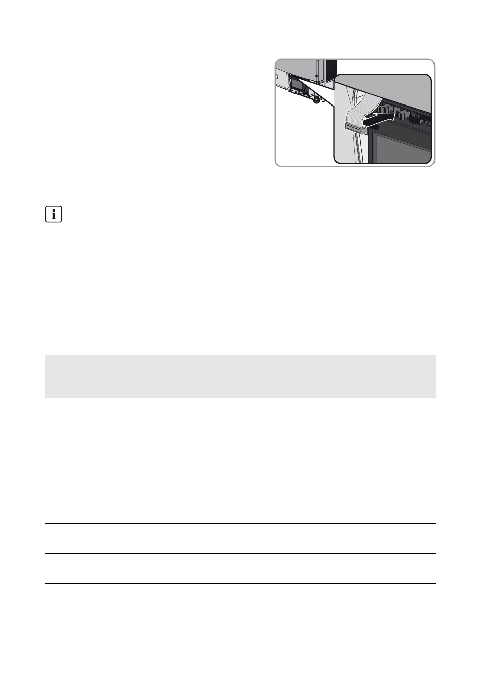
9. Insert the plug from the multifunction relay ribbon
cable into the left-hand pin connector on the display
assembly. You have to press apart the lock hooks
on the pin connector in order to insert the plug.
☑ After inserting the plug, the lock hooks close.
4.5 Selecting the Operating Mode
You can choose between the following operating modes:
Error message required by standard
In some countries, signaling of errors is required by standards, e.g. IEC 62109-2.
This requirement can be met in one of two ways:
• Operate the multifunction relay in the operating mode Fault indication (FltInd) and
connect a display to the multifunction relay that signals an error or the undisturbed
operation of the inverter.
• Activate the error alarm in Sunny Portal (see the Sunny Portal user manual at
www.SunnyPortal.com for information on receiving error alarms via Sunny Portal).
This requires the inverter to be registered on Sunny Portal.
Operating mode of
multifunction relay
(Mlt.OpMod)
Description
Fault indication (FltInd)
The multifunction relay controls a display device which,
depending on the type of connection, signals either an error or the
undisturbed operation of the inverter.
This operating mode is set by default.
Self-consumption
(SelfCsmp)
The multifunction relay switches the loads on or off depending on
the amount of power available from the PV array. If a battery is
integrated in the system, the multifunction relay will still switch the
loads on or off depending on the amount of power available from
the PV array, not from the battery.
Control via communication
(ComCtl)
The multifunction relay switches loads on and off according to
commands transmitted by a communication product.
Battery bank (BatCha)
The multifunction relay controls the charging of external batteries
depending on the amount of power available from the system.