SMA 485 Data Module Type B User Manual
Page 18
5 Electrical Connection
SMA Solar Technology AG
18
485BRD-10-IA-en-12
Installation Manual
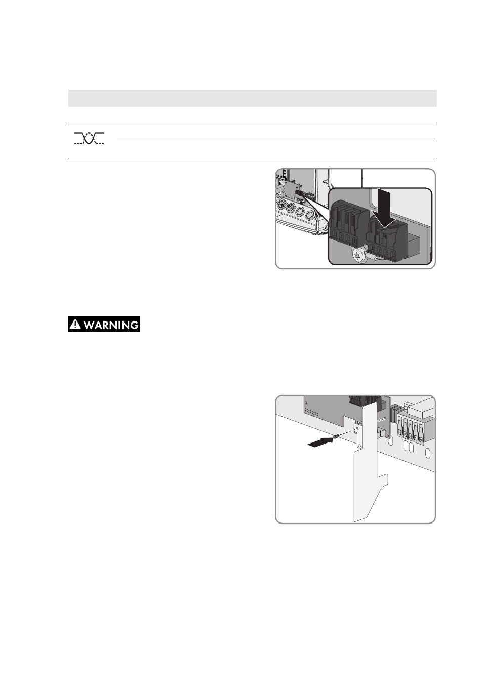
4. Connect the wire to the terminals of the spring clamp terminal and note down the colour of the
wires. The cables can be allocated to any spring-cage connector.
5. Close the spring clamp terminals.
6. Press each cable with the cable shield into the shield clamp.
8. Tighten the swivel nut of the cable gland.
9. Close and commission the inverter (see inverter installation manual).
10. Connect the cable end to the RS485 bus (for information on the terminal assignment and wiring
in the system, see the Technical Description "RS485 Cabling Plan").
Signal
485 data modules Insulated wire colour
RS485 bus
GND
5
5
Data+
2
2
Data-
7
7
7.
Electric shock due to live cables
If, during inverter operation, an insulated wire (L1, L2 or L3) should become detached from
the AC terminal, there is the risk that the cables of the RS485 communication become live.
Touching the cables can cause fatal electric shock.
• Attach the supplied plastic foil to the module
using the supplied expanding rivet. This
isolates the AC connection area in the
inverter from other terminals.