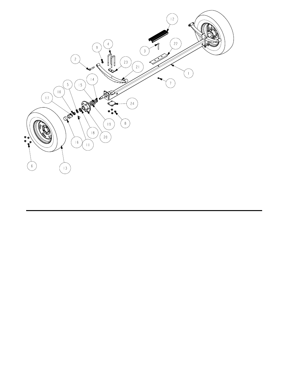
Material list for the sr-v1824 chasis – ShoreLand'r SR- PWV1824 User Manual
Page 4
REF# PART#
DESCRIPTION .......................................... QTY
1
66154--
AXLE WMENT (74 WIDE) ......................... 1
2
0110170 HH 9/16-18 X 3 1/4 CS GR5 ..................... 2
3
0210130 CARR 3/8-16 X 3 3/4 GR5 ........................ 1
4
0310170 SUB 1/2" X 2-5/16"X6-1/2 .......................... 4
5
1340206 WASHER 1.5 OD X .765 ID X .186/.206 .. 2
6
1410229 HEX LUGNUT 1/2-20 13/16 OD Z&U ....... 10
7
1440101 FLANGE LOCKNUT SMALL 3/8-16 .......... 1
8
1440102 FLANGE LOCKNUT SMALL 1/2-13 .......... 8
9
1440259 HEX LOCKNUT 9/16-18 GRA ................... 2
10
1440349 HEX NUT SLOTTED PLAIN ..................... 2
11
1540038 COTTER KEY 1/8 X 1 1/2 ......................... 2
12
3510132 AXLE PAD 12IN BLK ................................ 1
13
4300218 ST185/80R13C TIRE/MSILVER DIR RIM ...... 2
14
4410089 SPINDLE SLEEVE 1 1/4-3/4IN BRG ....... 2
15
4410130 SEAL 1 3/8IN ............................................ 2
16
4410246 SL BEARING PROTECTOR BRA ............ 2
17
4410247 BEARING BUDDY - STAINLESS STEEL . 2
18
4440160 ROLLER BEARING 1 1/16IN .................. 2
19
4440170 ROLLER BEARING 1 3/8IN .................... 2
20
4470400 HUB 1 3/8 X 1 1/16 CAST ....................... 2
21
4610072 SPRING 5 LEAF HOOK ........................... 2
22
S-3387
2" PLASTIC CHANNEL BRACKET .......... 1
23
S-3409G SPRING CLAMP 1/4X1 1/2X4 ZYU ....... 2
24
S-3449G SPRING AND AXLE U-BOLT PLATE ........ 2
Made in the USA
Midwest Industries, Inc. Ida Grove, IA 51445 Tele: 712/364-3365
0002746
5/22/00
2001
Material List for the
SR-V1824 Chasis
Axle:
Place one of the spring bracket bushings (Ref.#73) into the rear of
the spring shackle and secure with a 9/16” X 3-1/4” hex bolt
(Ref.#23) and a 9/16” lock nut (Ref.#47). Repeat on the other side.
Position the axle under the frame, then hook the spring loop
around the bushing just installed. Raise the axle assembly up so
the front of the springs line up with the front spring bracket hole.
Insert the other two (2) 9/16” X 3-1/4” and 9/16” lock nuts. Tighten
all nuts and bolts but do not over tighten. Allow the spring room
enough to move.
Mount the tires and rims using 80-90 ft. lbs. torque on lug nuts
using a proper tightening procedure.
Bunk:
Mount and secure the 9’ bunk assemblies onto the 3-7/8” bunk
brackets (Ref.#8) using 3/8” X 1” hex bolts. Tighten with 3/8” flange
lock nuts. Be sure that the bunks are positioned so that the bunk
bracket attached to the bunk and the bracket attached to the frame
are mounted together so that you have metal to metal stops to
keep the bunks from pivoting too far. Tighten as far as possible but
still allow the bunk to fully pivot side to side.
Winch:
Mount the Profile 2000 winch assembly with jack on the tongue a
desired location that best fits your watercraft using three (3) 1/2” X
4” carriage bolts and 1/2” flange lock nuts. Install the winch handle
on the Profile 2000 winch shaft.
Assembly should be complete except for tightening some of
the bolts. These bolts were left loose to aid in adjusting the
trailer to the boat only. All bolts and nuts must be tightened
before towing.
NOTE: The law requires that the white ground wire on both
the tongue wire harness and vehicle harness be properly
grounded to respective trailer and vehicle frames.
Trailer Adjustments
Before adjusting the winch post check to see that the transom of
the boat is flush with rear of the bunks.
Place the boat onto the trailer so that it is resting on the bunks. The
transom must be flush with bunks at the rear of the trailer. Once
the boat is positioned as described above, make the following
adjustments.
Winch Post:
Slide the winch post into position. Note that the winch holder
(upper portion) must be positioned just above the bow eye. Run
the winch strap over the upper nylon bushing in the winch case and
secure to bow eye. Tighten all bolts on the winch post. Slip the
bow eye safety chain into the bow eye. Adjustment is complete.
Check the tongue weight.
continue from page 2