ShoreLand'r SMB10TM V.2 User Manual
Page 6
Midwest Industries, Inc.
Ida Grove, IA 51445
800.859.3028
www.shorelandr.com
0003920
Page
01/25/2008
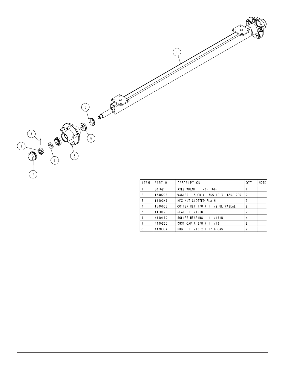
AXLE & WHEEL ASSEMBLY
Locate the axle for the trailer. Note that there isn’t a right or left to
the axle assembly. Place one of the springs on top of the spring
pad welded to the axle. Drop two (2) 3/8” x 2 3/16” x 2” U-bolts over
the springs and down through the holes in the spring pad. Secure
with 3/8” flange lock nuts. Repeat this process on the other spring
mounting it so that it is oriented on the axle the same as the first
spring.
Slip a spring bushing spacer into the rear of the spring bracket,
align the bushing with the hole in the bracket and secure in position
using a 1/2” x 3” hex bolt and 1/2” flange lock nut. Tighten. Repeat
on the other spring bracket.
Slide the axle assembly under the trailer frame, raise up and slide
the rear of the springs above the bushings just installed. Rotate the
assembly up until the front spring eyes align with the front holes in
the spring bracket. Insert a 9/16” x 3-1/4” hex bolt and secure with
a 9/16” lock nut. Tighten. Tighten the U-bolt attaching the springs
to the axles at this time and any other bolts that may have been left
loose for ease of assembly.
Place the tire and wheel assemblies on the hubs and secure with
the 1/2” tapered lock nuts.
TIRE & WHEEL ASSEMBLIES
Mount the tire and wheel assemblies using the 1/2” fine threaded
tapered lug nuts provided. Tighten to 80-90 ft/lb. of torque using the
rotation pattern as shown in the ShoreLandr’s Owners Manual.
Re-torque the lug nuts after 50 miles of driving and then periodi-
cally thereafter.