ShoreLand'r PVB1412 V.2 User Manual
Page 3
Midwest Industries, Inc.
Ida Grove, IA 51445
800.859.3028
www.shorelandr.com
0003881
Page 3
10/03/07
FINAL ASSEMBLY INSTRUCTIONS
Remove all banded items and the hardware bag from the frame.
Remove the parts and sort by size.
Tongue
Locate the tongue and install by sliding it in the front of the tongue
channel, continue to first crossmember as shown in Detail C. Insert
a 3/8” X 4” carriage bolt from the top down into the front crossmem-
ber and tongue. Secure with a 3/8” flange lock nut. Insert another
3/8” X 4” carriage bolt through the side of the tongue change cap on
the frame and into the tongue. Secure with a 3/8” lock nut.
Side Marker Light
Locate the side marker light holes on the side of the tongue. Mount
the amber side marker light to the tongue using two #10 x 3/4” self-
drill screw. Refer to Detail B for placement. Repeat on other side
of tongue.
Safety Chain
Insert a 3/8” X 1-1/4” hex bolt through a 3/8” flat washer, a safety
chain and another 3/8” flat washer (in placement order). Proceed to
insert this assembly into the lower hole on the front of the tongue.
Secure with a 3/8” flange lock nut on the inside of the tongue tube.
Refer to Detail A for placement. Repeat on other side of tongue.
Coupler
Mount the coupler to the top two holes on the front of the tongue.
Using two 1/2” x 1” hex bolts in the first two holes on the coupler/
tongue, secure with 1/2” flange lock nuts on the inside of the tongue
tube. The second hole on the tongue/coupler will be secured with
a 1/2” x 4” hex bolt and 1/2” flange lock nut on the inside of the
tongue tube. Refer to Detail A for placement.
Tongue Stand
Mount the tongue stand to the front under side of the tongue by
inserting the key lock into the key hole. Turn tongue stand and align
with front under side hole on the tongue. Place a 1/2” x 1” hex bolt
up through the tongue stand/tongue and secure with a 1/2” flange
lock nut on the inside of the tongue tube. Refer to Detail A for place-
ment.
Winch
Mount the winch stand to the tongue in location that would best fit
your watercraft. Secure with three 3/8” x 4” hex bolts and three 3/8”
flange lock nuts.
Mount the winch handle on the winch assembly using the hardware
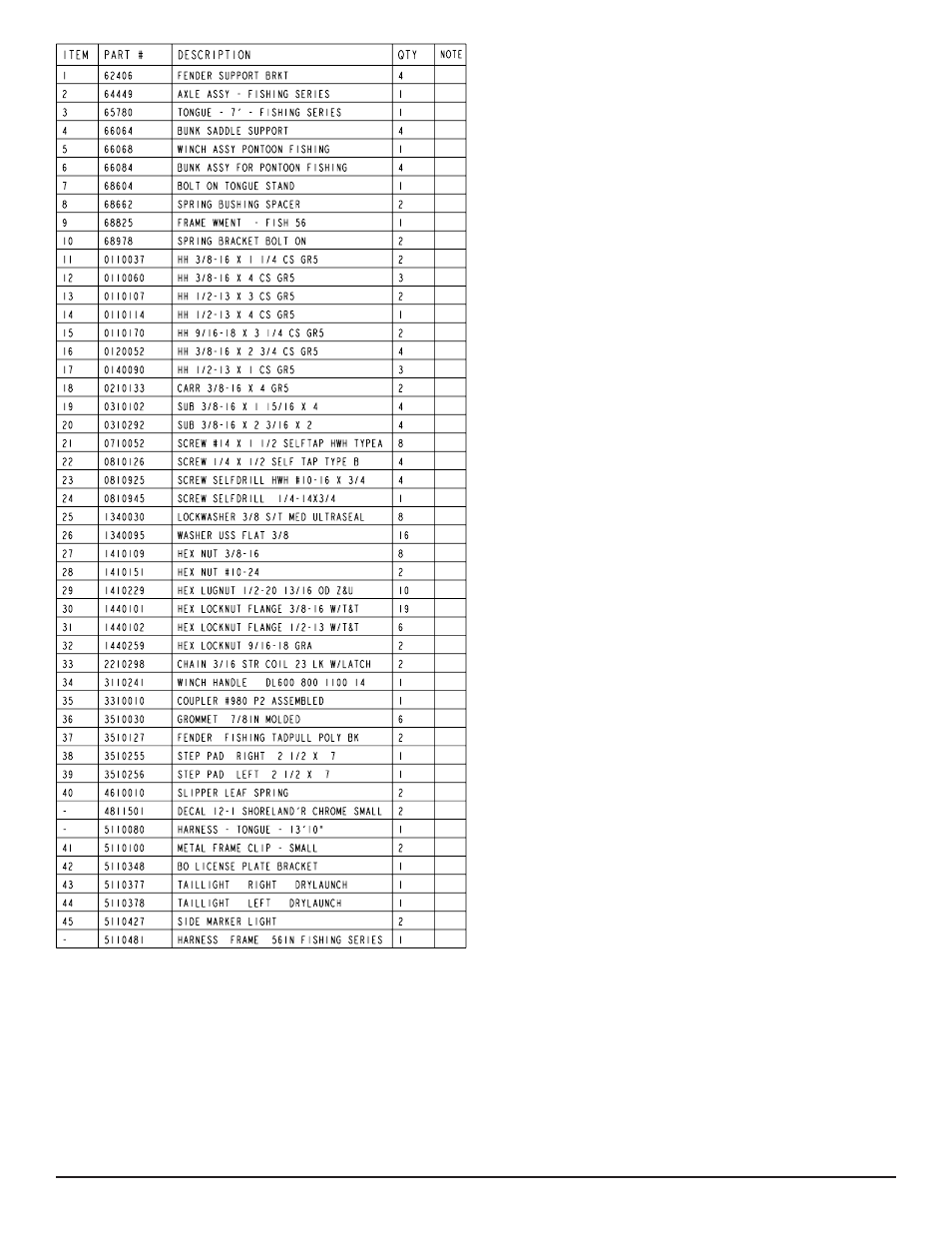
provided. Refer the parts drawing for placement.
Springs
Mount the leaf slipper springs to the top of the axle using two 3/8”
x 2-3/16” x 2” square u-bolts. Secure with 3/8” flange lock nuts. Re-
peat on opposite side of axle. Refer to Detail F for placement.
Axle
Place one spring bushing into the rear of the spring bracket and
secure with 1/2” x 3” hex bolt and 1/2” flange lock nut. Repeat on
opposite side of the trailer. Position the axle under the frame, slide
the slipper spring above the bushing. Raise the axle assembly up
so that the front of the spring line up with the front spring bracket
hole. Insert a 9/16” x 3-1/4” hex bolt and secure with a 9/16” hex
lock nut. Repeat on other side of the trailer. Refer to Detail E and
F. Do not overtighten. The springs must be able to react to road
variances.
Tire & Wheel Assemblies
Mount the tire and wheel assemblies using the 1/2” fine threaded
tapered lug nuts provided. Tighten to 85-95 ft/lb. of torque using the
rotation pattern as shown in the ShoreLandr’s Owners Manual.
Re-torque the lug nuts after 50 miles of driving and then periodi-
cally thereafter.
Tire Size and Carrying Capacity Chart
Tire Size ............................4.80 x 12B
GVWR ...............................1560 LB.
Carrying Capacity ..............1200 LB.
Axle....................................N/A
Refer to the tire side wall for correct tire pressure.