ShoreLand'r PS6X12SR V.1 User Manual
Page 2
Midwest Industries, Inc.
Ida Grove, IA 51445
800.859.3028
www.shorelandr.com
0004001
Page 2
REV C 10/01/2008
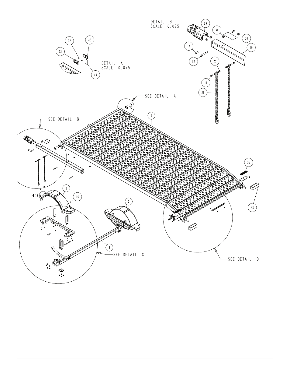
ASSEMBLY INSTRUCTIONS:
SAFETY CHAIN
Refer to Diagram B on page 2 for placement.
Insert a 3/8” X 1-1/4” hex bolt with 3/8” flat washer through the
safety chain. Insert this assembly through the lower hole on the
front of the tongue. Secure with a 3/8” flat washer and 3/8” flange
lock nut on the inside of the tongue tube. Repeat this procedure on
the other side of the tongue tube.
TONGUE
Refer to parts drawing on page 2 for placement.
Slide the tongue into the tongue channel on the frame assembly
and secure with two 1/2” X 4” hex bolts and 1/2” flange lock nuts.
FRONT STOP
Refer to Diagram A on page 2 for placement.
Mount the front stop weldment to the front of the frame using two
3/8” X 4-7/16” X 3” square u-bolts. The placement of the u-bolts will
go over the front frame tube weldment with the legs of the u-bolt
facing towards the inside of the frame. Secure with 3/8” flat wash-
ers, 3/8” lock washers and 3/8” hex nuts. Insert black plastic caps
on exposed tube ends.