Safety instructions – ShoreLand'r PWCD2213 V.1 User Manual
Page 9
Midwest Industries, Inc.
Ida Grove, IA 51445
800.859.3028
www.shorelandr.com
0003797
Page 9
05/01/07
FINAL ASSEMBLY INSTRUCTIONS
Remove all banded items from the frame and
sort hardware by size.
TONGUE
The trailer is designed with a swing tongue
as standard equipment. Rotate the swing
tongue into its towing position and secure in
place using the 5/8” x 6” hitch pin supplied
with the trailer. Secure with the hairpin cotter
key also provided.
SAFETY CHAINS
Locate the 1/2” x 5” hex bolt. Slip the bolt
through a 1/2” flat washer, then place through
the last link ofone of the safety chains.
Place the bolt with chain attached through
the hole provided in the bottom front of the
actuator mount on the tongue. Place the
second chain on the portion of the bolt ex-
tending through the other side of the tongue.
Place on another 1/2” flat washer and hex
lock nut. Tighten.
SPRINGS
Position the axle so it is properly aligned with
the trailer. Place the springs on the top side
of the spring pads welded to the axle. (See
chassis diagram). Note that the hook end of
the spring must be mounted to the rear of the
trailer. Place a spring clamp on the top center
of the spring as shown. Next place the 1/2” x
6-1/2” U-bolts down over the top of the spring
clamp, spring and axle as shown.
Place the spring and axle U-bolt plate onto
the ends of the two U-bolts just placed.
Secure in place with 1/2” lock nuts. Thread
onto the U-bolts but do not tighten securely
until the complete unit is in position on the
trailer. Repeat on the other spring.
AXLE
Place one of the spring bracket bushings into
the rear of the spring bracket and secure with
a 9/16” x 3 1/4” hex bolt and hex lock nut.
Repeat in other spring bracket.
Position the axle under the frame, then
hook the hook loop of the spring around the
bushings just installed. Note that if the axle
is positioned too low when trying to hook, the
hooks will not hook around the bushings.
Raise the front of the springs up so they
align with the front hole of the spring bracket.
Secure in place with 9/16” x 3-1/4” hex bolts
and lock nuts.
Tighten all axle U-bolts and spring bolts not
tightened at this time.
TIRE & WHEEL ASSEMBLY
Mount the tire and wheel assemblies us-
ing the 1/2” fine threaded tapered lug nuts
provided. Tighten to 85-95 ft./lb. of torque
using the rotation pattern as shown in the
ShoreLandr’s Owners Manual.
Re-torque the lug nuts after 50 miles of driv-
ing and then periodically thereafter.
WINCH POSTS
The winch posts can be mounted as far for-
ward on the mounting channels as possible
until the PWC’s are placed on the trailer.
Attach by placing the 3/8” bolts through the
holes in the bottom of the winch posts and
the mounting channels.
Place the winch handles onto the winch drive
shafts and secure using the 1/2 “ nuts pro-
vided. All other adjustments will be done after
the PWC’s are positioned on the trailer.
BUNKS: FRONT CROSSMEMBER
Outside PWC bunk brackets on each side
of the trailer:
Slide a 3/8” x 3-7/16” x 3” square U-bolt
(Item #11) over the front cross member so
the threaded end of the U-bolt is pointing
forward. Position the PWC bunk bracket on
the front side of the cross member so that
the dog leg end of the bracket is pointing
outward. Align two holes in the PWC bunk
bracket with the legs of the U-bolt, then
insert U-bolt through the holes in the PWC
bunk bracket and secure with 3/8” flange
SAFETY INSTRUCTIONS
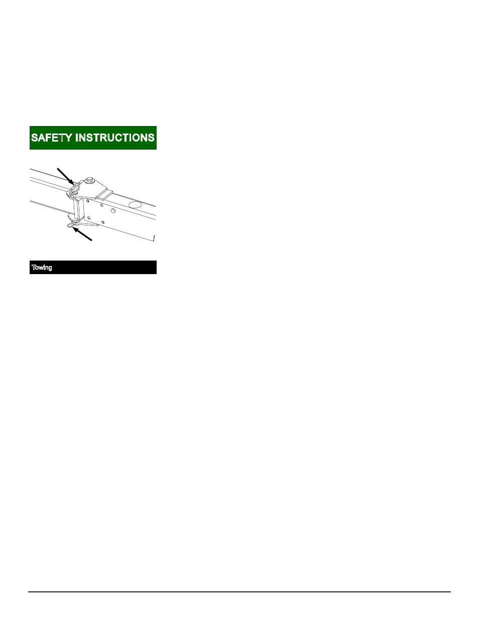
Towing
For safe and proper towing, hitch pin must be
positioned as shown and secured with hitch
pin clip.
USE ONLY THE HITCH PIN PROVIDED BY
THE MANUFACTURER.
Contact your
ShoreLand’r
dealer for
replacement parts.
04/2/07 4850422
Hitch
Pin
Hitch
Pin Clip
lock nuts. Repeat this process on the other
outside PWC bunk bracket on the front cross
member.
Inside PWC bunk brackets on each side
of the trailer:
Repeat the above process except point the
dog-leg of the PWC bunk brackets toward
the center of the trailer.
BUNKS: REAR CROSS MEMBER
Outside PWC bunk brackets on each
side of the trailer:
Slide a 3/8” x 3-7/16” x 3” square U-bolt
(Item #31) over the rear cross member so
the threaded end of the U-bolt is pointing
rearward. Position the PWC bunk bracket
on the rear side of the cross member so
that the dog leg end of the PWC bunk
bracket is pointing outward. Align two holes
in the PWC bunk bracket with the legs of
the U-bolt, then insert U-bolt through the
holes and secure with 3/8” flange lock nuts.
Repeat this process on the other
PWC bunk bracket on the rear cross
member.
Inside PWC bunk brackets on each side
of the trailer:
Repeat the above process except point the
dog-leg of the PWC bunk brackets toward
the center of the trailer.
Locate the bunk assemblies. Note that one
end of the bunks have a tie down bracket
fastened to it.
Position the bunk above the PWC bunk
brackets just installed so that the tie down
bracket is to the rear of the trailer. Align the
holes in the bunk brackets (Item #1) with
a hole in the PWC bunk brackets. Note
that the PWC bunk bracket must be on the
correct side of the leg of the bunk bracket
attached to the bunk so that the metal of
both brackets will hinge bind themselves
when the bunks are pivoted. This will keep
the bunks from pivoting too far when the
machines are removed from the trailer. At-
tach the two together using 3/8” x 1” hex
bolt and 3/8” flange lock nuts. Tighten but
do not over tighten. The bunks must be
allowed to pivot so they can conform to the
PWC boat bottom when it is placed on the
trailer. Repeat this process on the other
bunks.