Material list for the ss1110, Ss1110 shorelock’r – ShoreLand'r PWC1512 V.1 User Manual
Page 6
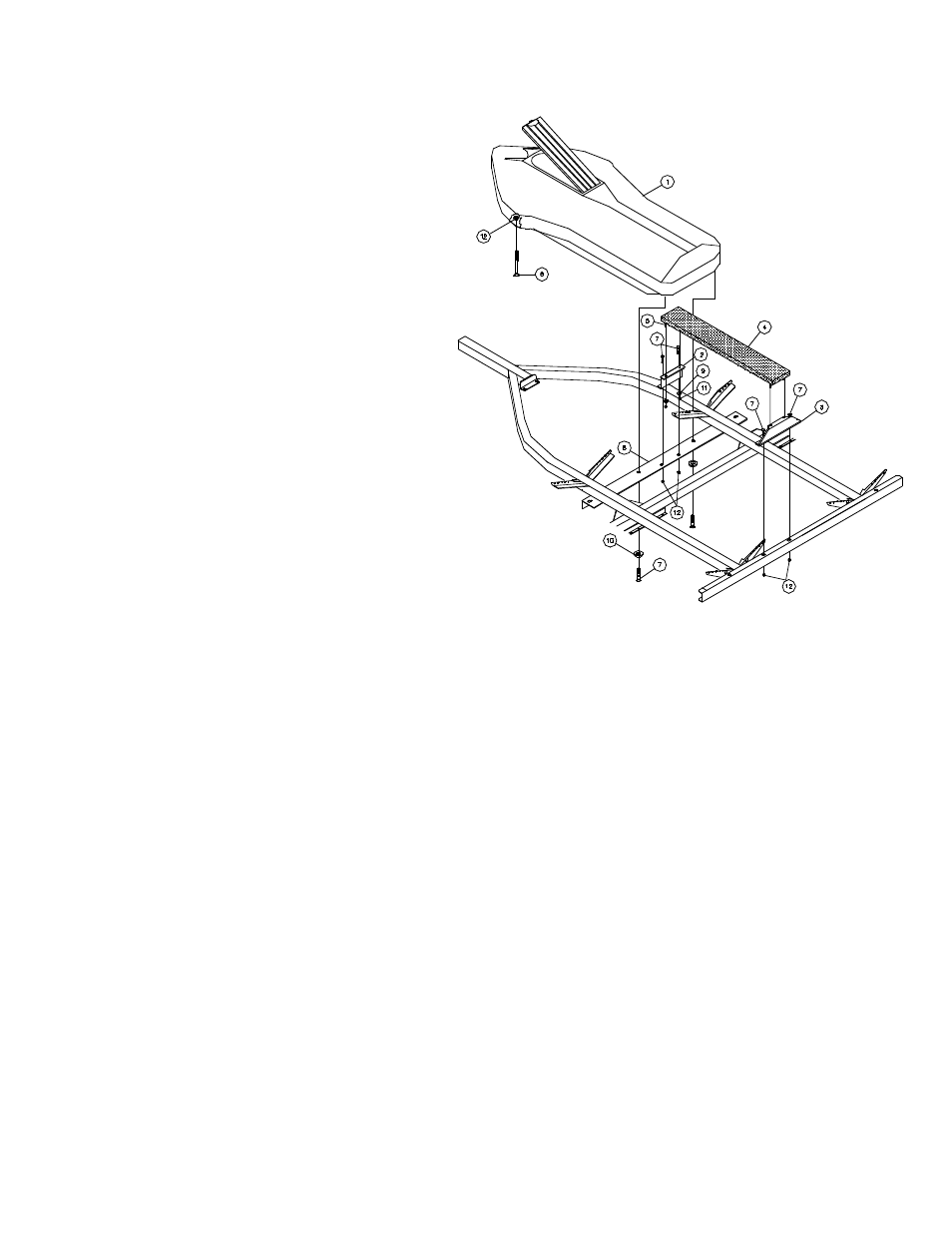
Material List for the SS1110
REF# PART#
DESCRIPTION
QTY
1
3510511
SHORELOCK’R W/LID ........................ 1
2
63058--
CENTER SUPPORT - PWC SC KIT .... 1
3
63059--
REAR SUPPORT - PWC SC KIT ......... 1
4
63083P
BUNK ASSY - PWC .............................. 1
5
0210125
3/8” X 2-1/2” CARRIAGE BOLT ............ 4
6
0110059
3/8” X 3-3/4” HEX BOLT ........................ 2
7
0140040
3/8” X 1” HEX BOLT .............................. 6
8
63397--
CROSSMEMBER ANGLE - PWC SC ... 1
9
1340030
3/8” MED. S/T LOCK WASHER ............ 4
10
1340095
3/8” USS FLAT WASHER ..................... 2
11
1410109
3/8” HEX FINISH NUT .......................... 4
12
1440101
3/8” FLANGE LOCK NUT ..................... 6
Assembly Instructions for the SS1110 Storage
Compartment Kit
1.
Remove the 3/8” nuts and lock washers from the u-bolt
that holds the winch posts to the main frame. Remove the
bottom support strap from the u-bolt.
2.
Install the cross member angle (Ref.#8) to the frame as
shown with the leg of the angle to the front with the u-bolt
that just removed in Step 1. Reinstall the bottom support strap.
Secure in place with the lock washers and nuts just removed.
Do not tighten at this time.
3.
Attach the center support walk board bracket (Ref.#2) to
the cross member with two (2) 3/8” X 1” hex bolts and 3/8”
flange lock nuts. Tighten.
4.
Place the ShoreLock’r in the frame so the front of the
box is resting on the frame and the rear is resting on the
cross member. Align the holes in the rear of the ShoreLock’r
with the slots in the cross member. Insert two (2) 3/8” X 1”
hex bolts with 3/8” flat washers into the nuts molded into the
ShoreLock’r .
5.
Position the front of the ShoreLock’r so that it is in the
center of the frame. Using a 13/32” drill nit, drill holes into the
ShoreLock’r by drilling from the bottom up through the holes
already in the frame. Install the 3/8” X 3-3/4” hex bolts into
the holes just drilled from the bottom up. Secure with 3/8”
flange lock nuts.
Now that he front of the ShoreLock’r is secured to the frame
in the front, position the rear cross member so that the bolts
are positioned in the center of the slotted holes front to rear.
Secure the cross member to the frame by tightening the
u-bolts in Step 2. Tighten the 3/8” X 1” hex bolts that secure
the ShoreLock’r to the cross frame. Note that the bolts
when tightened will allow movement between the
ShoreLock’r and the cross member. This is necessary to
accommodate for the expansion and contraction of the
ShoreLock’r .
6.
Install the rear support brackets (Ref.#3) to the rear cross
member of the trailer with two (2) 3/8” X 1” hex bolts and lock
nuts. Do not tighten. Mount the front of the walk board onto
the center support bracket using 3/8” lock washes and hex
nuts. Secure the rear support bracket into position and
secure with the bolts installed in the walk board and 3/8”
lock washers and hex nuts. Tighten all bolts at this time.
7.
Your ShoreLock’r has been designed so that the lid may
be locked to the main body by placing a padlock through the
hole in the latch installed in the front of the ShoreLock’r.
Your ShoreLock’r should be locked at all times to prevent
theft.
8.
Your ShoreLock’r is equipped with a snap tighten
expandable plug.
9.
Your ShoreLock’r is designed to carry approximately
100-125 pounds of gear. Exceeding this amount will void all
warranty and may cause damage to your ShoreLock’r..
SS1110 ShoreLock’r
Midwest Industries, Inc.
Ida Grove, IA 51445
(800)859-3028
www.shorelandr.com
0002865