ShoreLand'r SLV2313BLW V.2 User Manual
Page 9
Midwest Industries, Inc.
Ida Grove, IA 51445
800.859.3028
www.shorelandr.com
0003415
Page 9
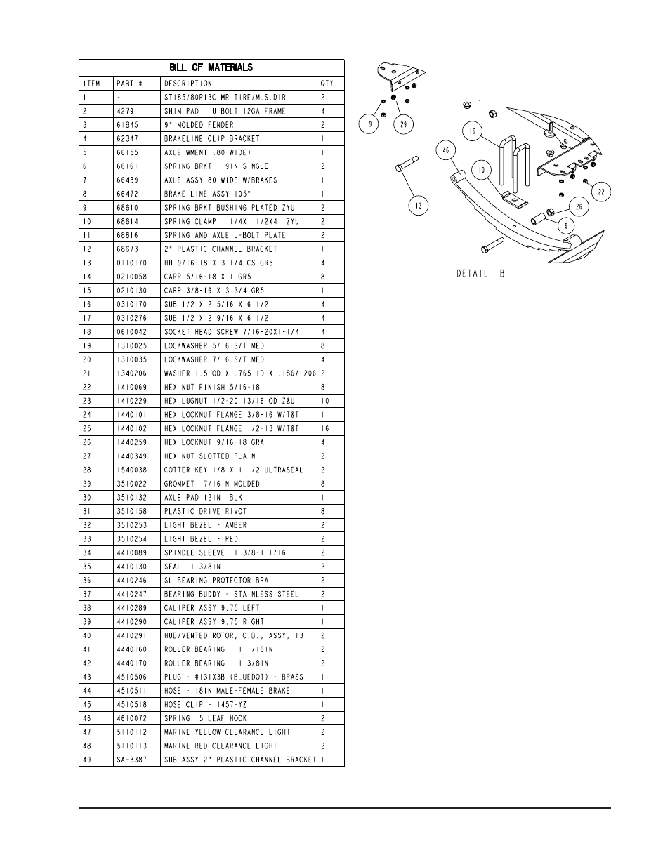
ONE AXLE BRAKE INSTALLATION
Cut the tape securing the brake line hose to the axle. Re-
move the brass plug from the port in the brass block on the
right brake caliper. Thread in the male end of the brake hose
and tighten to 6-8 ft. lb. or else 72-96 in. lb. of torque.
DO NOT OVER TIGHTEN. Over tightening will cause the
brass block to crack and then leak.
Place the other end of the hose through the hole in the brake
line clip bracket and secure with the U-shaped hose clip pro-
vided.
Remove the plastic cap from the end of the frame brake line
coming out of the side frame. Uncoil the brake line so that it
reaches the end of the hose just attached to the brake line
clip bracket. Thread the brake line fitting into the brake line
hose. Tighten.
NOTE: The axle has brake fluid installed in the calipers and
the axle line when it is assembled at the factory. This is done
to protect the inner parts of the brake system during shipping
and storage. The complete brake system including the axle
MUST be re-bled to ensure that all air has been removed
from the brake system.
For bleeding instructions see the UFP brake bleeding man-
ual or the ShoreLand’r Disc Brake Manual.
Fill the actuator reservoir with brake fluid and bleed the line
per the instructions in the Brake Manual.
TIRE & WHEEL ASSEMBLY
Mount the tire and wheel assemblies using the 1/2” fine
threaded tapered lug nuts provided. Tighten to 85-95 ft./lb.
torque using the rotation pattern as shown in the Shore-
Landr’s Owners Manual.
Re-torque the lug nuts after 50 miles driving and then peri-
odically thereafter.