Diagram a – ShoreLand'r SLR12 User Manual
Page 2
Midwest Industries, Inc.
Ida Grove, IA 51445
800.859.3028
www.shorelandr.com
0003304
Page 2
REV A 2/06/06
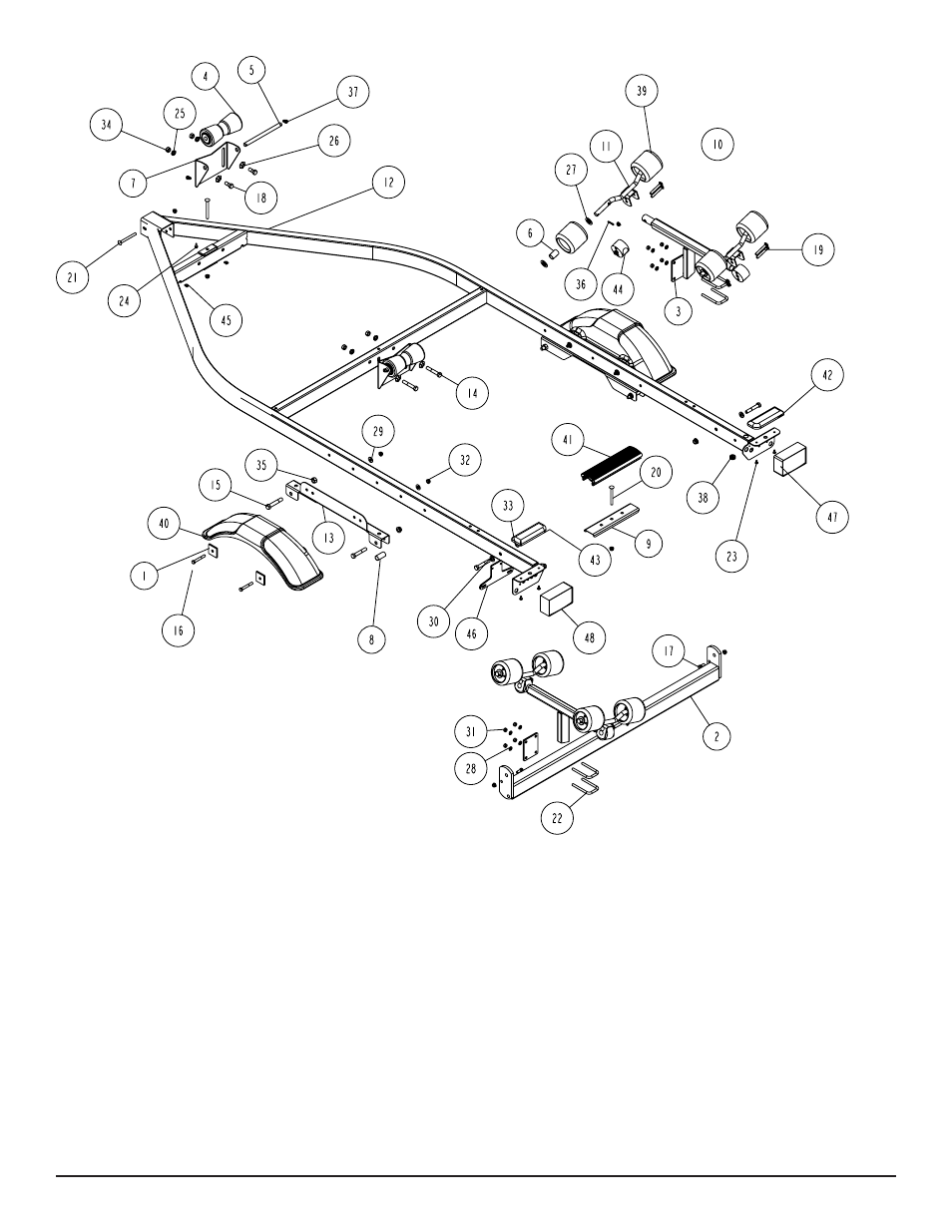
Diagram A
Keel Roller Installation
Remove the keel roller assembly from the hardware box. Position it
on the back side of the front cross member of the frame as shown
in Diagram A. Attach it to the cross member by placing a 1/2” star
washer on a 1/2” x 1-1/4” hex bolt. Align the slot in the keel roller
bracket with the hole provided in the cross member. Insert the bolt
into the hole and attach to the cross member with a 1/2” lock wash-
er and hex nut. Repeat this process on the second bolt used to
attach the keel roller assembly to the cross member.
Repeat the above process on the second keel roller assembly.
The keel roller assembly can be left loose until the boat is placed on
the trailer for final adjustment.