Trailer adjustments – ShoreLand'r SLB80TBB User Manual
Page 4
Made in the USA
Midwest Industries, Inc. Ida Grove, IA 51445 (800)859-3028
0002874
www.shorelandr.com
REV B 11/13/00
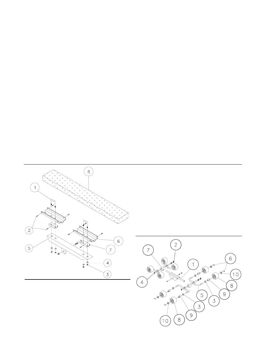
REF# PART#
DESCRIPTION
QTY
1
0310224
1/2 X 3-9/16 X 1-1/2 SQUARE U-BOLT ........... 2
2
0810920
1-1/4 PH SCREW ............................................... 8
3
1440102
1/2 FLANGE LOCK NUT .................................... 4
4
3810097
.515 ID X 11/16 OD X 7/16 LONG BUSHING .. 4
5
61767--
BUNK BRACKET ................................................. 1
6
S-3263
GALV. 16 BUNK BRACKET ............................... 2
7
S-3264
GALV. BUNK SUPPORT PIVOT ........................ 2
8
61778--
36 BUNK ASSEMBLY W/BRACKETS ............... 1
Bunk Material List: 61778--P
REF# PART#
DESCRIPTION
QTY
1
S-3485
24-1/2 ROLLER ARM ......................................... 1
2
0210127
3/8-24 X 3 CARRIAGE BOLT - 1 THREAD ...... 4
3
1310121
3/4 FLAT WASHER; ALUM. ............................... 8
4
1440100
3/8 HEX LOCK NUT ........................................... 4
5
S-3368
19-1/2 ROLLER PIN........................................... 4
6
1540350
BULL RING .......................................................... 8
7
S-3184
PLASTIC MOLDED SWIVEL BLOCK .................. 2
8
S-3382
5 ROLLER W/MOLDED HUB ............................. 8
9
S-3383
MOLDED ROLLER BUSHING ............................. 8
10
S-3384
SPECIAL FLAT WASHER ................................... 8
Roller Material List: 60617--
Place the roller assemblies on the rear support tube (Ref.#95).
Secure the roller assemblies in the outside holes of the rear
support tube with 1/2 X 4-1/2 hex bolts and 1/2 flange lock nuts.
Front Roller Cradle:
Install the front roller cradle on the front crossmember and secure
with a 5/8 X 12 hex bolt and 5/8 hex lock nut. Do not over
tighten, the roller cradle should freely tilt aft and the stop built into
the roller cradle frame should contact the front of the
crossmember if it is installed properly. (The front roller cradle is
normally factory installed.)
Assembly should be complete except for tightening some of
the bolts. These bolts were left loose to aid in the adjusting
the trailer to the boat only. All bolts and nuts must be
tightened before towing. NOTE: The law requires that the
white ground wire on both the tongue wire harness and the
vehicle harness be properly grounded to the respective trailer
and vehicle frames.
Trailer Adjustments
Place the boat onto the trailer so that it is resting on either on the
bunks or the roller in the back and on the front keel support pad up
front. Position the boat front to back by having the center of the
rear roller approximately 4 from the transom. The bunk model is
more flexible in its adjustment from to back but the boat should be
positioned so that the transom is being supported by the bunk.
Once the boat is positioned as above make the following
adjustments.
Rear Racks:
Position the racks in the back so that they are located between the
keels or strakes and so that they wont interfere when loading and
unloading. Once positioned, tighten the u-bolts in the mounting
brackets. The up-down adjustment in the rear adjustable mounting
bracket should be in its down position whenever possible to keep
the center of the gravity lower to the ground for better trailering.
The upper position should be used only when fender or frame
clearance is needed.
Bunk:
Position the rear of bunks as previously describe in the rear rack
section. Position the front portion of the bunk in the desired area
and adjust vertically for proper pressure of the bunks to the boat
hull. CAUTION: Do not over adjust the front portion of the bunks
which may lift the keel off the front keel roller cradle.
Winch Post Adjustment:
Once the boat is positioned on the trailer, adjust the winch post to
the boat. Loosen the three (3) 1/2 X 4 hex bolts and move the
winch bracket so that the top rubber bow roller is just above the
bow eye. Tighten.
Slide the winch post assembly against the boat. Tighten the u-
bolts. Adjustment is complete.
NOTE: Double-check all nuts, bolts and fasteners - they must
be tightened before towing.