ShoreLand'r SLB68T User Manual
Page 8
Midwest Industries, Inc.
Ida Grove, IA 51445
(800)859-3028
www.shorelandr.com
M304025
Page 8
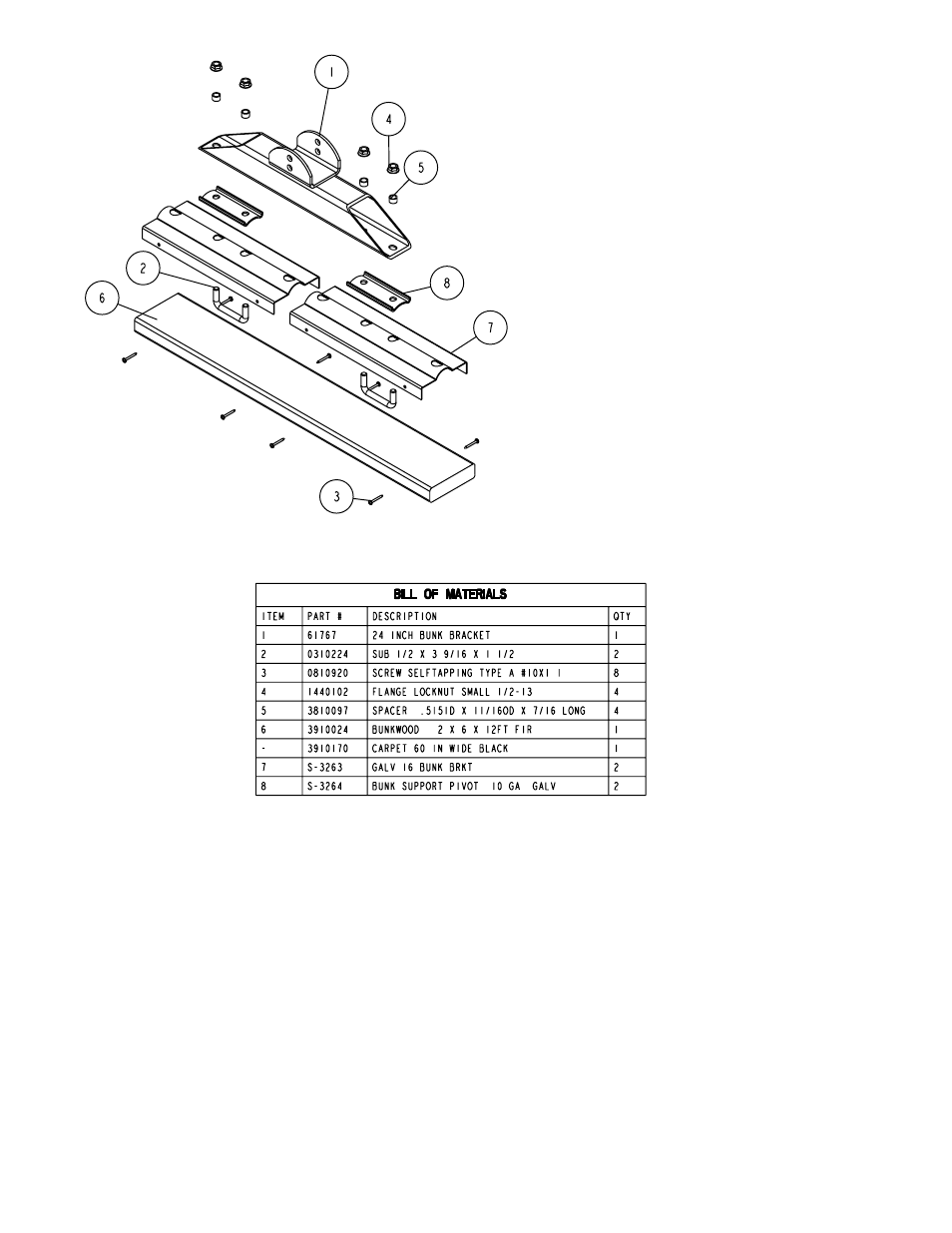
RB Bunk Assembly
Locate the support arms bundle. Place one of the arms into the factory installed mounting bracket on the rear pivot with the
ends curved up as shown. Secure in the bracket with two (2) 1/2” x 4” carriage bolts and hex lock nuts. See Detail B. Tighten.
Place one of the bunk assemblies on the end of the support arms just installed. Line up the top hole in the mounting bracket
with the hole in the support arm and secure with a 1/2” x 4-1/2” hex bolts and hex lock nuts. Tighten. Repeat on the other end
of this support arm. Repeat this complete process on the other support arm.
Note that the bunk assemblies have two height adjustments. The instructions are to install them in the lowest position to keep
the center of gravity as low as possible for towing. If required for fender clearance, the bunks can be installed in the raised
position by mounting the bunk assemblies to the bunk support arms using the lower mounting hole.
Roller Arm Assembly
Locate the support arms bundle. Place one of the arms into the factory installed mounting bracket on the rear pivot with the
ends curved up as shown. Secure in the bracket with two (2) 1/2” x 4” carriage bolts and hex lock nuts. See Detail B, Page
2. Tighten.
Place one of the roller assemblies on the end of the support arms just installed. Line up the hole in the mounting bracket with
the hole in the support arm and secure with a 1/2” x 4-1/2” hex bolts and hex lock nuts. Tighten. Repeat on the other end of
this support arm. Repeat this complete process on the other support arm.