Diagram b – ShoreLand'r LEB22CLW V.2 User Manual
Page 4
Midwest Industries, Inc.
Ida Grove, IA 51445
800.859.3028
www.shorelandr.com
0003282
REV B 2/07/06
Page 4
FINAL ASSEMBLY INSTRUCTIONS
Remove the hardware bag from the frame, remove parts and sort
by size.
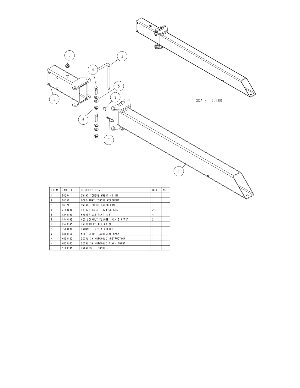
TONGUE
The tongue is shipped separate from the frame. Locate the ap-
propriate tongue and install by sliding it in the front of the tongue
channel.
Line the holes in the tongue with the holes in the tongue
channel. Install the 1/2” x 4” hex bolt in the front cross hole and
secure with a 1/2” lock nut.
Remove the wire harness from the rear of the tongue. Place the
wire harness and the brake line (If equipped with brakes)
through the hole provided in the tongue cover plate.
Secure the tongue cover plate in position with the same 1/2” x
1-1/2” hex bolt that secures the back on the tongue to the
tongue channel of the frame. Secure with a 1/2” lock nut.
Tighten both bolts just installed.
P l u g t h e t o n g u e w i r e h a r n e s s e n d s i n t o t h e f ra m e
h a r n e s s e s by m a t c h i n g c o l o r s a n d e n d s. P u s h t h e
extra wire provided either into the rear of the tongue
o r e l s e r e m o ve t h e g r o m m e t s i n t h e s i d e f r a m e s
and place the extra wire in the side frames. Replace
grommet just removed.
SAFETY CHAINS
Locate the 1/2” x 5” hex bolt. Slip the bolt through a 1/2”
flat washer, then place through the last link of one of the
safety chains.
Place the bolt with chain attached through the hole
provided in the bottom front of the actuator mount on the
tongue. Place the second chain on the portion of the bolt
extending through the other side of the tongue. Place on
another 1/2” flat washer and hex lock nut. Tighten.
Diagram B