Enerco MHVFB10LPI User Manual
Page 11
Installation instructions and Owner’s Manual
11
Make sure grille guard is in place before running heater.
If screen or grille guard is removed for servicing it must
be replaced prior to operating the heater.
WARNING: Failure to keep the primary air
opening(s) of the burner(s) clean may result in
sooting and property damage.
CLEANING ODS/PILOT AND BURNER
•
Use as vacuum cleaner, pressurized air or small
soft bristled brush to clean.
CLEANING BURNER PILOT AIR HOLE INLET
We recommend that you clean the unit ever 2,500 hours
of operation or every three months. We also recommend
that you keep the burner tube and pilot assembly clean
and free of dust and dirt. To clean these parts we
recommend using compressed air no greater than 30
psig.
This can be done by using a vacuum cleaner in the blow
position, using compressed air in a can, please follow
the directions on the can. If you don’t follow directions
on the can you could damage the burner or pilot assem-
bly. In addition, the directions that follow should also be
followed.
1. Shut off the unit, including the pilot. Allow the
unit to cool for at least thirty minutes.
2. Inspect burner and pilot for dust and dirt.
3. Blow air through the port/slots and holes in the
burner.
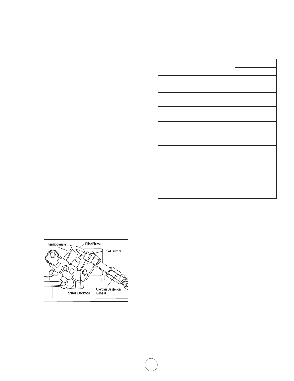
A yellow tip on the pilot flame indicates dust and dirt in
the pilot assembly. To clean the pilot assembly find the
small pilot air inlet hole about two inches from where the
pilot flame comes out of the pilot assembly (see Pilot Air
Inlet Hole in figure 25). With the unit off, lightly blow air
through the air inlet hole. You may blow through a
drinking straw if compressed air is not available.
Figure 25
CLEANING HEATER CABINET
Air passageways
•
Use a vacuum cleaner or pressurized air to clean
Exterior
•
Use a soft cloth dampened with a mild soap and
water mixture. Wipe the cabinet to remove dust.
SPECIFICATIONS
MHVFB10LP
BTU (Available)
10,000
Type of Gas
LP-Gas Only
Ignition
Piezo
Pressure Regulator Setting
10 Inches of
Water
Inlet Gas Pressure (Maximum) 14 Inches of
Water
Inlet Gas Pressure (Minimum)
11 Inches of
Water
Burners / Orifice nozzles
1
Thermostatic Control
No
Clearances: inches (mm)
Top
36 (915)
Sides
6 (152)
Floor (min. to top of carpet)
2 (51)
Fabric / flammable objects
36 (915)