Grass Valley Trinix Back-Up Power Supplies Nov 16 2012 User Manual
Page 39
Trinix — Installation and Service Manual
39
Installation Procedure - DV-33128 and DV-33256 Units
Note
The power supply frame should be mounted in the same equipment rack as
the Trinix, but it may be mounted in an adjacent rack if necessary. The cable
provided for connection to the Trinix is approximately ten feet (3 m) long.
Note
No special ventilation spacing is needed for these frames since the airflow is
from front to back.
b.
Test the external supplies prior to connecting to the Trinix router.
Temporarily apply electrical tape each of the DC output connectors
(red, blue, white, yellow) to isolate them to prevent shorting out.
Apply power to the external power supplies.
c.
Using a voltmeter, verify that the external frame’s output voltage
measures between 47 and 52 VDC.
d.
Unplug the external power supplies AC power cords.
e.
Unscrew the external supplies restraining screws and slide the
supply out of the chassis 1 inch.
CAUTION The following step will interrupt all signals passing through the router until
power is restored.
2.
Proceed as follows:
a.
Power down the router by unplugging the AC cord of each of the
internal power supplies.
b.
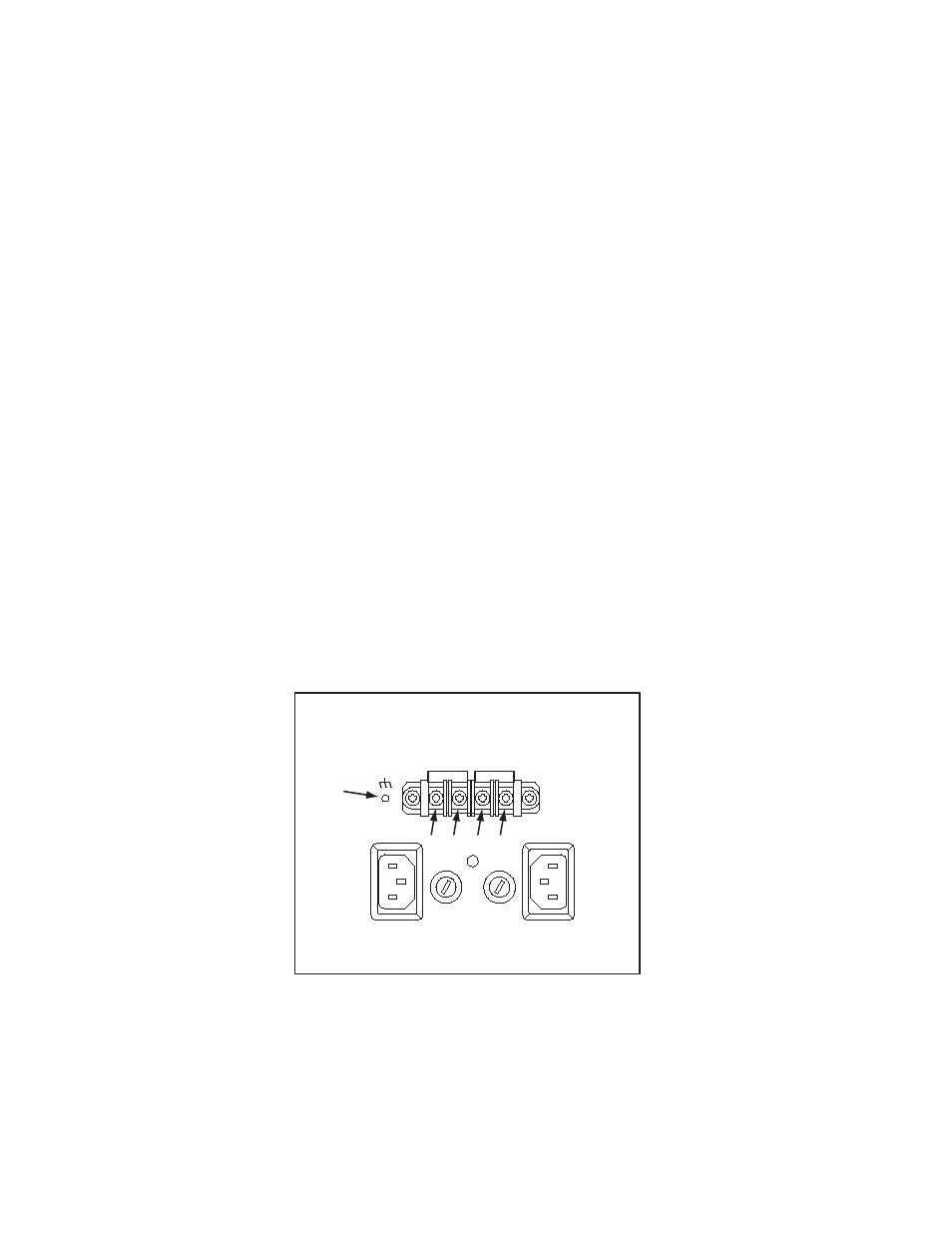
On the rear of the Trinix PS chassis, locate the “DC IN +” and “DC
IN -” terminal blocks. See
.
Figure 2. Power Connections Showing Reference Numbers Used for this Document
c.
Remove the “DC IN +” and “DC IN -” screws (2), (3), (4), and (5).
d.
Locate the DC power ground stud (1). Use a nut driver to remove
one nut (only) and one washer (only) from the stud.
DC IN -
DC IN +
PS B
PS A
(1)
(2)
(3)
(4)
(5)
8443_07