Grass Valley Profile Composite I/O User Manual
Page 35
Installing the Analog Composite I/O Board
Analog Composite I/O Installation
35
4. Install the blank circuit board brackets (if necessary) in the empty board slots
on the rear panel.
5. Refer to “Audio Clock Cabling” beginning on page 20 and connect audio
clock cables from the Analog Composite I/O board to the appropriate clock
connectors on the ASPB or the RECORD connectors on the Audio I/O
boards.
6. Use the Torx tool with the T10 tip to reinstall the rear board hold-down
bracket (see Figure 2, page 7).
CAUTION: To prevent damage to the Monitor board, a short board extension
on the front hold-down bracket must not be installed at the Monitor board
location.
7. If necessary, reconfigure the front board hold-down, moving or removing
short board extensions.
8. Use the Torx tool with the T10 tip to reinstall the front board hold-down
bracket (see Figure 2, page 7).
9. Use the Torx tool with the T10 tip to reinstall the rear top cover and then the
front top cover.
10.Apply the stick-on labels at the appropriate location in the Profile chassis
rear panel to identify the location of the Analog Composite I/O board and
any board you repositioned.
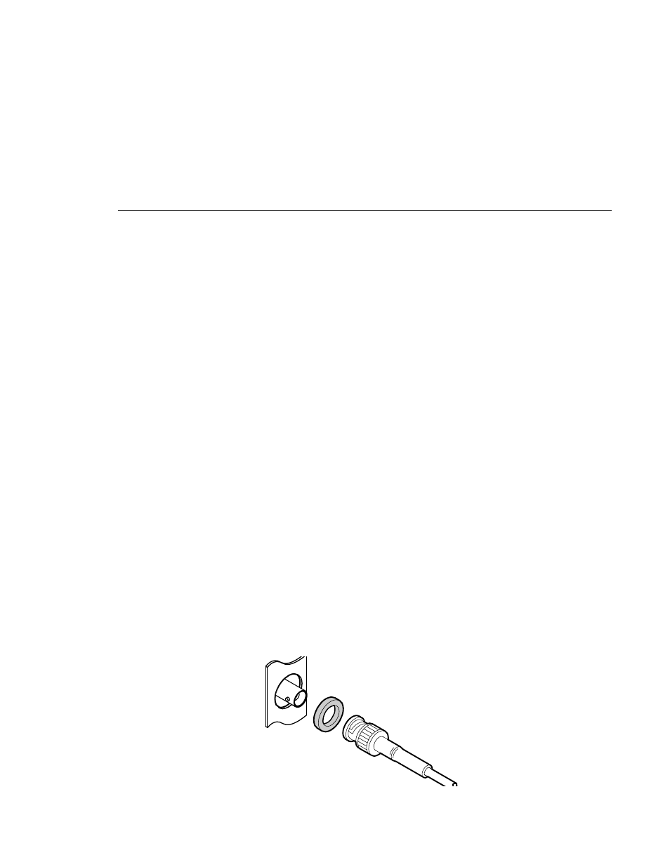
11.Reinstall the Profile chassis in the rack and reconnect all cables previously
removed. Before attaching cables to the BNC connectors, install the mesh
washers as shown in Figure 8.
Figure 8. Installing Mesh Washers