Bypassing & isolating – Emerson 7ADTB User Manual
Page 16
BYPASSING & ISOLATING
(continued)
3---7
RETURN TO SERVICE continued*
This procedure explains how to return the Bypass Switch
Handle to the OPEN position. The Bypass Handle must
be in the CLOSED position (yellow indicator on NOR-
MAL or EMERGENCY) and the Isolation Handle must
be in the CONN position (window). See Figures 3–20,
3–21, and 3–22.
You can only bypass to the same source
that the ATS is connected. Solenoid
interlock prevents incorrect operation.
1
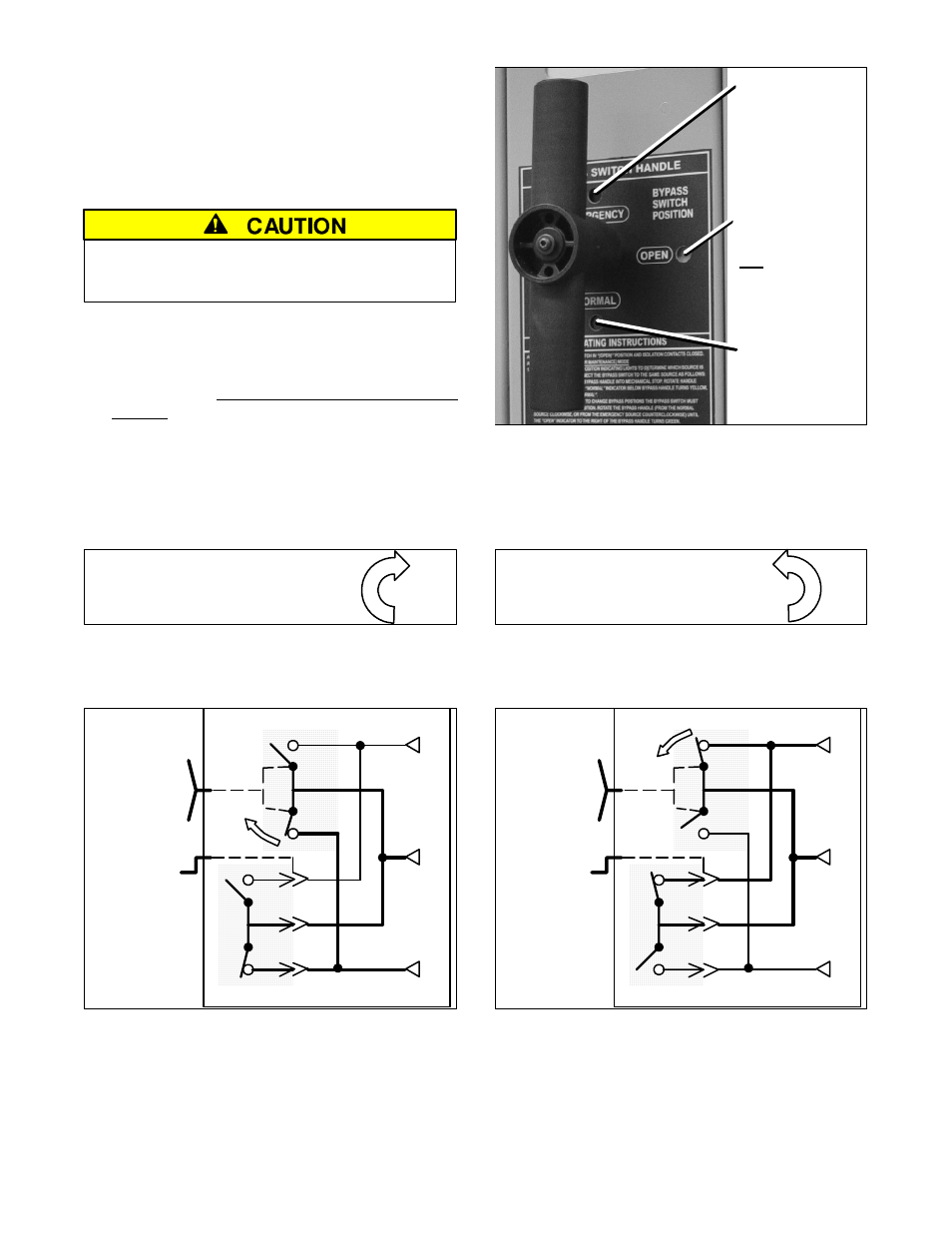
Observe which Bypass Switch Position indicator is
yellow (NORMAL or EMERGENCY) at the Bypass
Switch Handle. This indicates the source connected
to the load.
2
Un–Bypass to same source as the Bypass Switch
Position as follows (select Normal or Emergency).
Window indicator
shows green
when the ATS is
not bypassed.
Window indicator
shows yellow
when ATS is
bypassed to
Emergency.
Window indicator
shows yellow
when ATS is
bypassed to
Normal.
Figure 3–20. Bypass Handle and position indicators.
To Un–Bypass Normal Source*
To Un–Bypass Emergency Source*
(Load connected to Normal Source)
The Transfer Switch Connected To Normal light is on
and Transfer Switch Connected To Emergency light is off.
(Load connected to Emergency Source)
The Transfer Switch Connected To Emergency light is on
and Transfer Switch Connected To Normal light is off.
Turn the handle clockwise.*
Turn the handle counterclockwise.*
Turn* the Bypass Handle clockwise until the Bypass
Switch Position shows OPEN (green window indicator).
The Bypassed to Normal light should go off and the Not
In Automatic light should go off.
E
L
N
Turn
Bypass
Handle
clockwise.
ATS
Bypass Switch
Figure 3–21. Un–Bypass Normal diagram.
Turn* the Bypass Handle counterclockwise until the
Bypass Switch Position shows OPEN (green window
indicator). The Bypassed to Emergency light should go off
and the Not In Automatic light should go off.
E
L
N
ATS
Bypass Switch
Turn
Bypass
Handle
counter-
clockwise.
Figure 3–22. Un–Bypass Emergency diagram.
The Automatic Transfer & Bypass–Isolation Switch should be left in this position.
* NOTE
: When Accessory 40*B (reversed Normal & Emergency connections) is specified,
the handle push–pull operation is reversed. Follow instructions on the door.