Crosspoint module, Autotiming and chrominance/luminance split, Crosspoint module -16 – Grass Valley 1200 Installation User Manual
Page 90: Autotiming and chrominance/luminance split -16, Figure 3-6, Figure 3-6. crosspoint module
3-16
Section 3 Ñ Functional Description
Crosspoint Module
Autotiming and Chrominance/Luminance Split
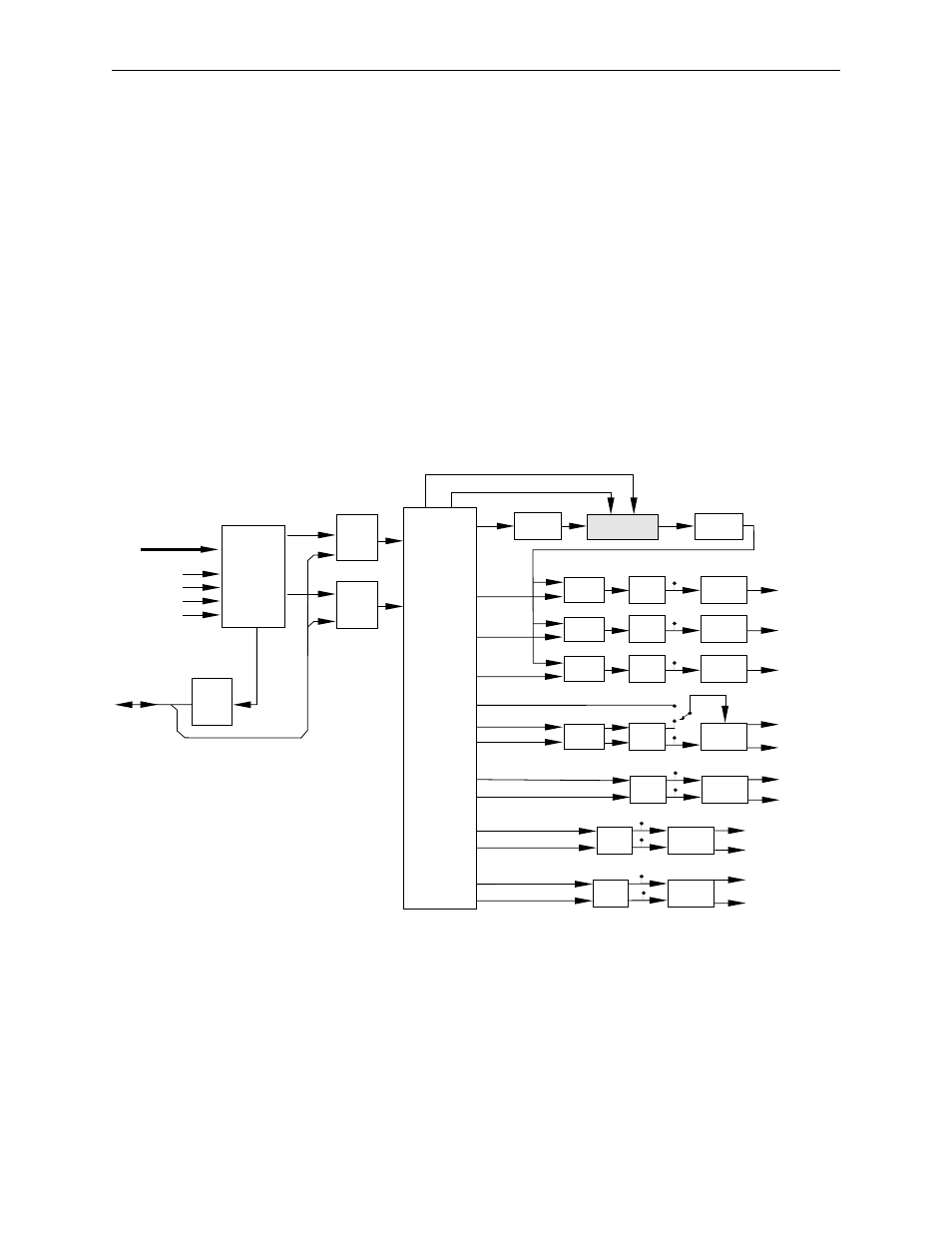
On the Crosspoint Module (Figure 3-6) the video first enters a circuit which
auto-times all of the input signals to the reference black signal then splits
the signal into luminance and chrominance signals. The key signals are
handled the same way except that they are split into key and depth.
Auto-timing is done by locating the horizontal interval of the video signal
and comparing it to H Blanking generated from the input reference black.
This data is sent to the Control Processor Module which then sends delay
data to a variable delay. The variable delay uses the data to delay the signal
so that all of the video sources are timed.
Figure 3-6. Crosspoint Module
CROSSPOINT
MATRIX
16 X 16 X 10 X 2
TX
RECLOCK
SELECT
DELAY
RX
RECLOCK
TX
RECLOCK
Y, C
Y, C, K
K1 DEPTH
K2 DEPTH
CHROMA KEY
SUBMODULE
SELECT
DELAY
TX
RECLOCK
SELECT
DELAY
TX
RECLOCK
LATCH
DELAY
TX
RECLOCK
DELAY
TX
RECLOCK
DELAY
TX
RECLOCK
DELAY
TX
RECLOCK
Y, C, K
Y, C, K
Y, C
Y, C or K, D
Y, C
K
Y, C
K
Y
C
Y, C, K
Chroma Key Xpts
Test
Header
Key 2
Key 1
DSK Key
Mask/Depth Key 1
Depth Key 2
Aux 1
Aux 2
Background A
Background A Key
Background B
Background B Key
BUFFER
DELAY
D1 DECODER
DELAY
Y
C
Delay Count
From CPU
Phase Count
to CPU
Clk In
Clock
HBI
50/60
27 MHz D1 In
Typical 1 of 16
Circuits Shown
To / From CPU
C Dual Link Channel B
C Dual Link Channel A
Y MASK