Control panel stripe-pcu connections – Grass Valley Kayenne K-Frame Installation Planning Guide Dec 03 2014 User Manual
Page 38
38
KAYENNE K-FRAME — Installation Planning Guide
Section 4 — Control Surface Installation
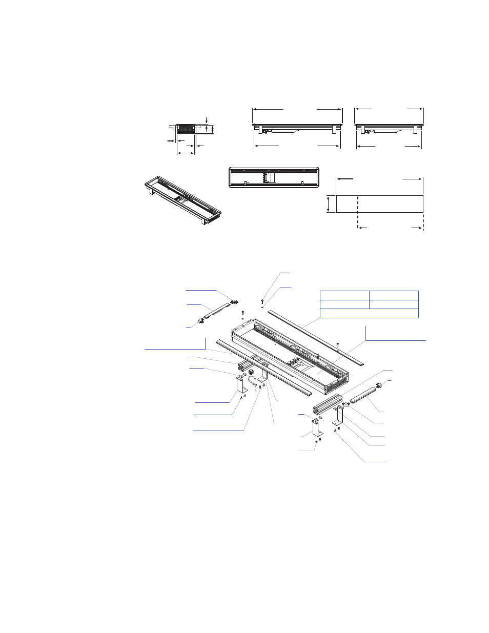
Separately Mounted Local Aux Stripe (35 & 25 Models)
Figure 28. Local Aux Stripe Separate Installation Dimensions
Figure 29. Local Aux Stripe Support Structure, Tray, and Trim
Control Panel Stripe-PCU Connections
Connectors on the outside bottom of the Stripe connect to the PCU, using a
special multi-pin cable that carries both power and communications.
CAUTION Do not connect or disconnect the multi-pin cables linking a Kayenne Control
Panel tray and PCU while the PCU is powered up. Damage to the equipment
can result.
156.5 +/-1 mm
6.2+/-.04 in.
591.5 +/-1 mm
23.3 +/-.04 in.
Local Aux 25 Panel Cutout
Aux Panel
Installed Separately
Local Aux 35 Panel Cutout
783.5 +/-1 mm
30.8 +/-.04 in.
8623266_30
781.5 mm
30.8 in.
Local Aux 35 Width
813.7 mm
32.0 in.
589.5 mm
23.2 in.
Local Aux 25 Width
621.7 mm
24.5 in.
154.7 mm
6.1 in.
15.2 mm
0.60 in.
15.8 mm
0.62 in.
10.3 mm
0.4 in.
74.0 mm
2.9 in.
850 0 4960
4x
850 0 4420
4x
855 7 1480
855 7 1480
855 7 1480
855 7 1480
855 7 3180
855 7 3180
850 06460
2x
850 06460
2x
850 06460
2x
850 06460
2x
862 0 3180
2x
862 0 3180
2x
862 0 3180
2x
862 0 3180
2x
855 7 2850
855 7 2850
855 7 2850
855 7 2850
H O U SI N G C P L. A UX
855 7 258 0 - 35 A U X B U TT ON
855 7 259 0 - 25 A U X B U TT ON
855 7 2710
855 7 2710
855 7 3060 - 35 A U X B U T T ON
855 7 3070 - 25 A U X B U T T ON
35 A U X B U TT ON
25 A U X B U TT ON
Silkscreen Kayenne Logo
855 7 3000
855 7 3010
8623266_31_r2