K-frame controller connections, Figure 10. k-frame 6-ru, rear view, Boot mode dip switch power switch – Grass Valley K-Frame Installation Planning Guide Jul 07 2014 User Manual
Page 27
K-FRAME — Installation Planning Guide
27
6-RU Compact Video Processor
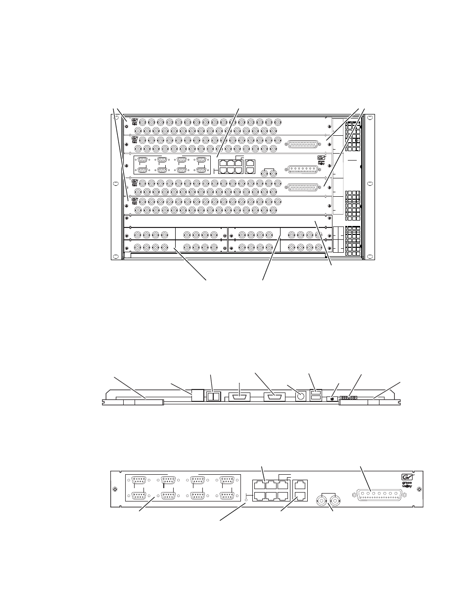
Figure 10. K-Frame 6-RU, Rear View
K-Frame Controller Connections
Figure 11. K-Frame Controller Board, Inside Chassis
Figure 12. Controller I/O Connections, Rear of Chassis
R
8
Mod I/O 3
Mod I/O 4
R9
Mod I/O 2
R7
R6
Mod I/O 1
R5
OUTPUTS
17 - 32
R4
INPUTS
33 - 64
R1
OUTPUTS
1 - 16
R2
INPUTS
1 - 32
R3
CONTROL I/O
CAUTION
Turn off power
before removing
or installing
Control I/O
in slot R3.
OUTPUTS
16
15
14
13
12
11
10
9
8
7
6
5
4
3
2
1
OUTPUTS
16
15
14
13
12
11
10
9
8
7
6
5
4
3
2
1
INPUT
OUTPUT
4
3
2
1
4
3
2
1
INPUT
OUTPUT
4
3
2
1
4
3
2
1
INPUT
OUTPUT
4
3
2
1
4
3
2
1
INPUT
OUTPUT
4
3
2
1
4
3
2
1
TALLY/GPI
INPUTS
32
31
30
29
28
27
26
25
24
23
22
21
20
19
18
17
16
15
14
13
12
11
10
9
8
7
6
5
4
3
2
1
TALLY/GPI
INPUTS
32
31
30
29
28
27
26
25
24
23
22
21
20
19
18
17
16
15
14
13
12
11
10
9
8
7
6
5
4
3
2
1
DC IN
LINK/ACTIVITY
OFF-10/AMBER-100/GREEN-1000
LAN
IMAGE STORE
MULTI
VIEWER
ANALOG
REFERENCE
DIAGNOSTIC
MODE
8
7
6
5
4
3
2
2
4
6
1
3
5
1
SERIAL PORTS RS422/485
8875_08
Output Video
(16 outputs each)
Up to 2 modules
Module 4 Module 1
Modular I/O
Up to 4 modules
Control I/O
(DC power in, Reference,
Ethernet and Serial ports)
Input Video
(32 inputs with
1 Tally/GPI each)
Up to 2 modules
(blank panel for
unused area)
ON
OFF
Boot Mode
DIP Switch
Power
Switch
8875_10
LEDs (15)
Test Points
with LEDs (9)
and Text Display
Reset
Button
RS-232
PS2
Keyboard
VGA
USB
(two ports, usable
with door closed)
USB
(two ports)
NOTE: Ports and indicators here are intended only for diagnostic and service procedures.
DC IN
LINK/ACTIVITY
OFF-10/AMBER-100/GREEN-1000
LAN
IMAGE STORE
ANALOG
REFERENCE
DIAGNOSTIC
MODE
8
7
6
5
4
3
2
2
4
6
1
3
5
1
SERIAL PORTS RS422/485
8875_18
Illuminated LED indicates
Port 1 is in diagnostic mode
Reference
Image Store Ethernet
(data transfer)
Serial Ports (8)
RS422/486
Ethernet (6)
(communications)
DC Power In
(from Power Supply)