Figure 5. k-frame 13-ru, rear view – Grass Valley K-Frame Installation Planning Guide Jul 07 2014 User Manual
Page 23
K-FRAME — Installation Planning Guide
23
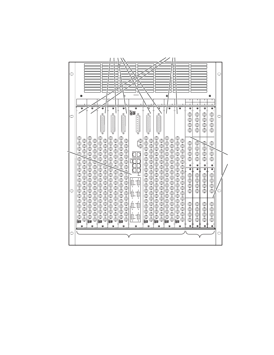
13-RU Standard Video Processor
Figure 5. K-Frame 13-RU, Rear View
R11
Mod I/O 1
Mod I/O 2
R12
Mod I/O 4
R14
Mod I/O 6
R16
Mod I/O 8
R18
R13
Mod I/O 3
R15
Mod I/O 5
R17
Mod I/O 7
R2
OUTPUTS
17 - 32
R1
OUTPUTS
1 - 16
R5
INPUTS
65 - 96
R4
INPUTS
33 - 64
R3
INPUTS
1 - 32
R10
OUTPUTS
49 - 64
R9
OUTPUTS
33 - 48
R8
INPUTS
129 - 160
R7
INPUTS
97 - 128
R6
CONTROL I/O
CAUTION
Turn off power before removing or
installing Control I/O in slot R6.
OUTPUTS
16
15
14
13
12
11
10
9
8
7
6
543
2
1
OUTPUTS
16
15
14
13
12
11
10
9
8
7
6
543
2
1
TA
LL
Y/GPI
INPUTS
32
31
30
29
2
8
27
26
25
24
23
22
21
20
19
1
8
17
16
15
14
13
12
11
10
9
8
76
5
4
3
2
1
TA
LL
Y/GPI
INPUTS
32
31
30
29
2
8
27
26
25
24
23
22
21
20
19
1
8
17
16
15
14
13
12
11
10
9
8
76
5
4
3
2
1
TA
LL
Y/GPI
INPUTS
32
31
30
29
2
8
27
26
25
24
23
22
21
20
19
1
8
17
16
15
14
13
12
11
10
9
8
76
5
4
3
2
1
TA
LL
Y/GPI
INPUTS
32
31
30
29
2
8
27
26
25
24
23
22
21
20
19
1
8
17
16
15
14
13
12
11
10
9
8
76
5
4
3
2
1
TA
LL
Y/GPI
INPUTS
32
31
30
29
2
8
27
26
25
24
23
22
21
20
19
1
8
17
16
15
14
13
12
11
10
9
8
76
5
4
3
2
1
OUTPUTS
16
15
14
13
12
11
10
9
8
7
6
543
2
1
OUTPUTS
16
15
14
13
12
11
10
9
8
7
6
543
2
1
INPUT
OUTPUT
43
2
1
43
2
1
INPUT
OUTPUT
43
2
1
43
2
1
INPUT
OUTPUT
43
2
1
43
2
1
INPUT
OUTPUT
43
2
1
43
2
1
INPUT
OUTPUT
43
2
1
43
2
1
INPUT
OUTPUT
4
3
21
4
3
21
INPUT
OUTPUT
4
3
21
4
3
21
INPUT
OUTPUT
4
3
21
4
3
21
DC IN
LINK/ACTIVITY
OFF-10/AMBER-100/GREEN-1000
LAN
IMAGE ST
ORE
MUL
T
I
VIEWER
ANALOG
REFERENCE
DIAGNOSTIC
MODE
8
7
6
5
4
3
2
24
6
13
5
1
SERIAL POR
T
S RS422/4
8
5
Output Video
(16 pairs of identical
outputs each)
Up to 4 modules
Modular I/O
Up to 8 modules
Module 1
Module 8
Control I/O
(DC power in,
Reference,
Ethernet and
Serial ports)
Input Video
(32 inputs with
1 Tally/GPI each)
Up to 5 modules
Rear Slots R1 - R10
Slots R11 - R18
8875_04