Cabling, Configuration, Operation – Grass Valley Kalypso Shot Box Option User Manual
Page 7: Reset shot box
Kalypso & Zodiak Shot Box Option Instruction Manual
7
Configuration
Cabling
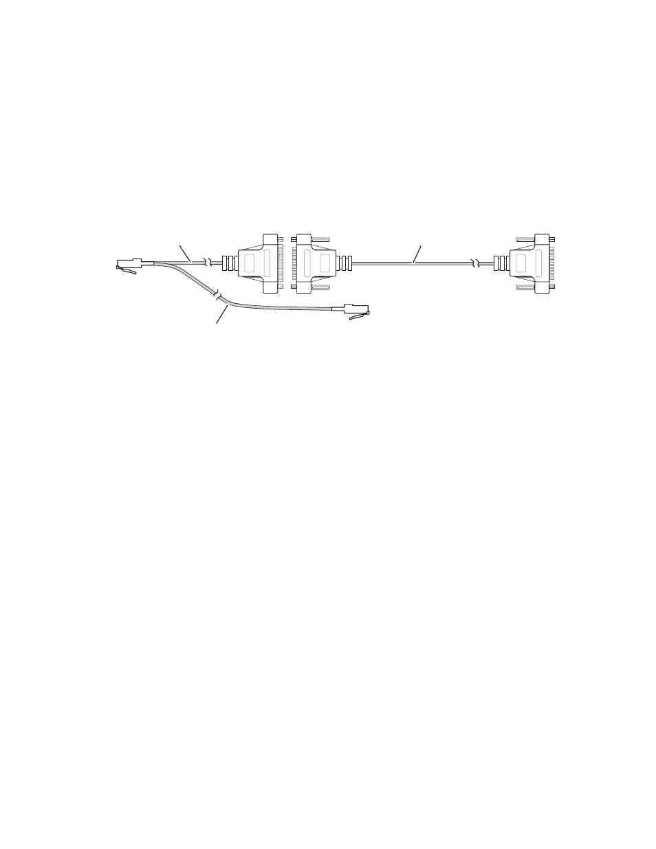
The provided cables connect the Main panel, Shot Box, and Video Pro-
cessor frame as shown in
Figure 4
. Power passes from the Main panel to the
Shot Box. To support power distribution, the short cable connects to the
Main panel and the long cable connects to the Shot Box. If the Shot Box will
be placed more than 3 m (10 ft)
from the Main panel, an optional cable kit
is available. Contact your local Thomson Grass Valley sales office for
details.
Figure 4. Shot Box Cables and Connections
Configuration
Shot Box control of the system is configured the same as editor control.
1.
Go to the Ports & Device Definition menu (accessed via
Eng Setup
,
Ports
& Devices
) and assign an Editor device to the Video Processor frame port
you attached the Shot Box cable to. Its settings should be 38.4k Baud,
Odd Parity.
2.
Activate editor control by going to the External Device Enables menu
(accessed via
Extern Device
,
Enables
) and turn on the
Editor Controls Switcher
button.
3.
If necessary, reset the Shot Box (see below).
Operation
Reset Shot Box
When the Video Processor frame is reset or powered off and on, it can lose
communication with the Shot Box (the Editor Interface state may turn off).
The Shot Box panel must be reset to restore communication. The Shot Box
can be reset by cycling power to the unit, or via keystrokes on the panel.
Male
To Video Processor
Frame Editor Port
16 m (52 ft)
To Shot Box
To Main Panel
Satellite Port
3 m (10 ft)
0619_05_07_r2
0.3 m (1 ft)
Female
Male