Channel select mode (csm) led is on (described in, For the following descrip, Ment. refer to – Grass Valley 8964MON User Manual
Page 16
16
8964MON Instruction Manual
Configuration
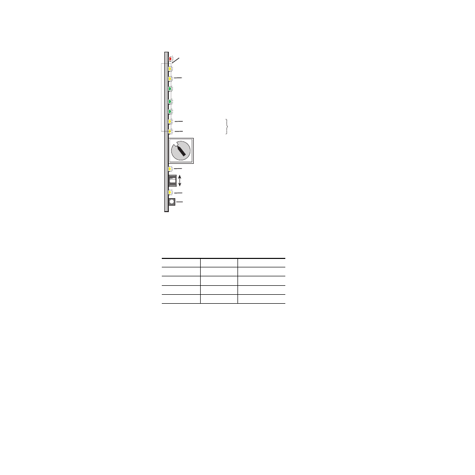
Figure 5. Onboard Configuration Components – Front View
Refer to
for reading the CM1 and CM0 active channel LED indica-
tors.
Table 4. CM1 and CM0 LED Table
CM1 LED State
CM0 LED State
Channel Control
Off
Off
Channel 1 is active
Off
On
Channel 2 is active
On
Off
Channel 3 is active
On
On
Channel 4 is active
SW1 – 16-position Function rotary switch – accesses 3 banks of
controls. Bank selected is indicted by state of 2ND LED.
SW3 – Paddle switch for incrementing parameter values (Parameter mode)
or selecting active channel (CSM, Channel Select Mode)
SW2 – Pushbutton switch to toggle between Parameter
and CSM modes
Ejector Tab
2ND LED – Not Used
8367_04
0
1
2
3 4
5 6 7
8
9
A
B
CD
E
F
CONF – Yellow LED on indicates module is initiating,
changing operating mode, or updating firmware
CM1 – Yellow LED
CSM LED – on in Channel Select Mode (use paddle to select channel)
CM0 – Yellow LED
Indicate active channel control (see table in text)