Service – Grass Valley 8920MUX User Manual
Page 37
8920MUX Instruction Manual
37
Service
Service
The 8920MUX modules make extensive use of surface-mount technology
and programmed parts to achieve compact size and adherence to
demanding technical specifications. Circuit modules should not be ser-
viced in the field.
If your module is not operating correctly, proceed as follows:
•
Check frame and module power and signal present LEDs. If module
power has failed, check Fuse F1 (see
).
•
Check for presence and quality of input signals.
•
Verify that source equipment is operating correctly and the AES/EBU
input stream is 48 kHz and synchronized with the SD video input.
•
Check cable connections.
•
Check output connections for correct I/O mapping (correct input con-
nector is used for the corresponding channel output).
for the location of PWR LED and
for
proper LED indications.
If the module is still not operating correctly, replace it with a known good
spare and return the faulty module to a designated Grass Valley repair
depot. Call your Grass Valley representative for depot location.
Refer to the
at the front of this document for the
Grass Valley Customer Support Information number.
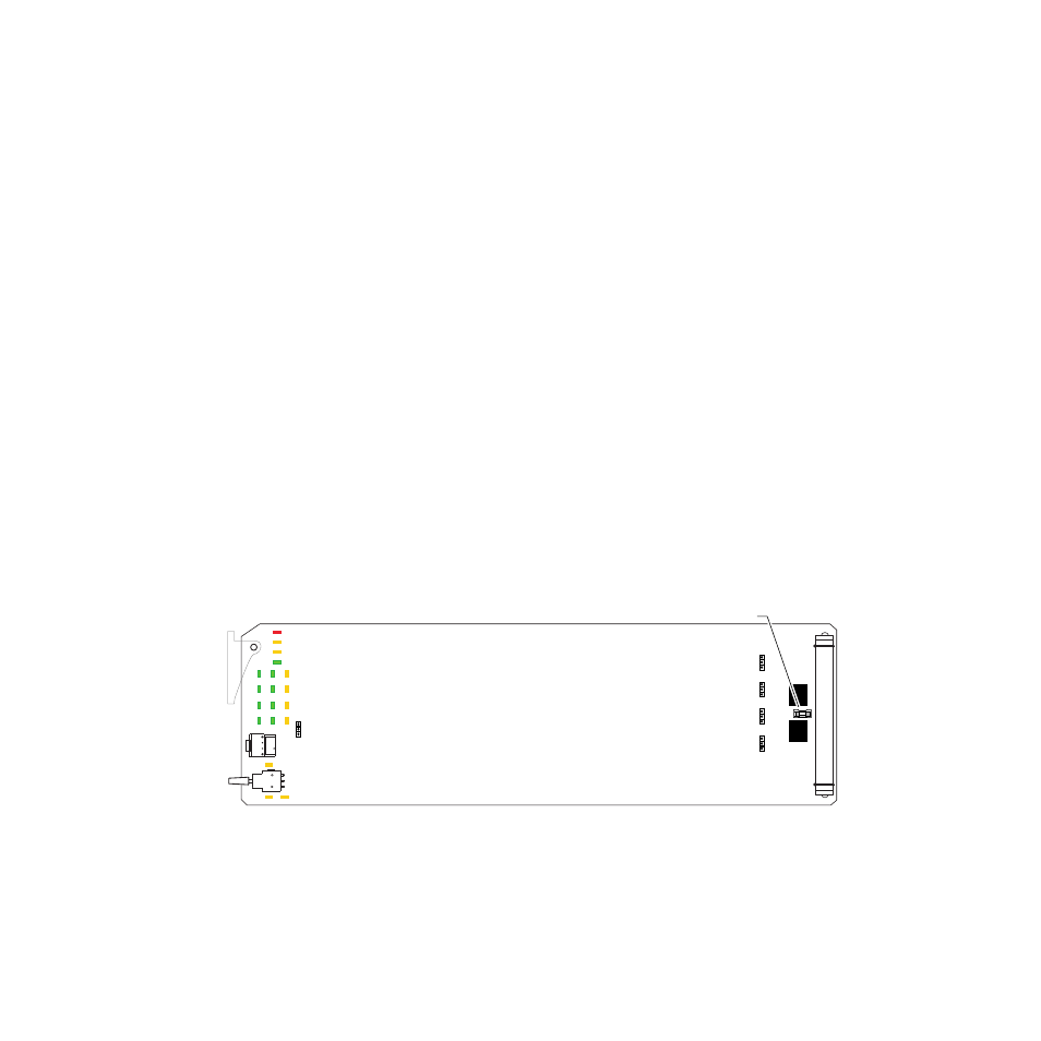
Figure 18. 8920MUX Module Fuse Location
8037_09
JP10
JP1
JP5
JP7
JP8
Fuse: 2 A FAST, 125 V
F1