Installation, On-board jumper settings – Grass Valley 8901 User Manual
Page 9
8901/8902/8906 Instruction Manual
9
Installation
Installation
Installation of the 8900 Analog Video DA modules is a process of:
1.
Setting on-board module jumper settings for desired operation
(
),
2.
Placing the module in the proper video frame slot (
3.
Cabling and terminating signal ports (
).
The DA module can be plugged in and removed from the frame with
power on. When power is applied to the module, LED indicators reflect the
initialization process (see
).
On-board Jumper Settings
Each 8900 Analog Video DA module requires jumper settings to determine
the desired operating modes as outlined in
.
illustrates each of the on-board jumpers on the circuit
board. Note that depending on the model, some components may not be
present. For details on setting each jumper, refer to the specific jumper
headings given in this section.
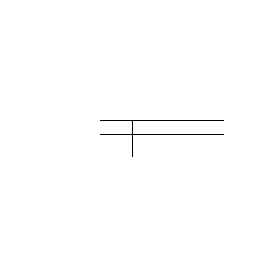
Table 2. On-board Jumper Settings
Jumper/Function
8901
8902
8906
J2 – Equalization
N/A
0 – 500’ or 500 – 1000’
(0 – 150 m or 150 – 300 m)
0 – 500’ or 500 – 1000’
(0 – 150 m or 150 – 300 m)
J4 – Coupling
DC or AC
Coupling
DC Restore, DC, or AC coupling
DC Restore, DC, or AC coupling
J5 – Clamp (8906)
N/A
N/A
Clamp On or Off,
Fast or Slow clamp
JP3– White Clip (8906)
N/A
N/A
On or Off