Functional description, Analog reference input selector – Grass Valley 8900FSS User Manual
Page 14
8
8900FSS Instruction Manual
8900FSS Frame Synchronizer Submodule
Functional Description
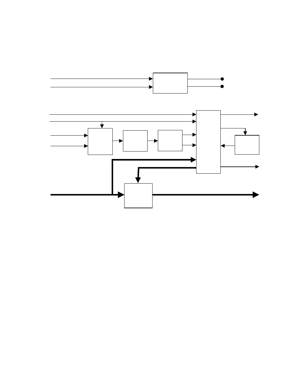
Refer to the block diagram in
while reading the following func-
tional description.
Figure 4. 8900FSS Frame Synchronizer Submodule Block Diagram
Analog Reference Input Selector
The analog reference video signals are connected to a high input imped-
ance multiplexer that selects the appropriate input source. A removable
jumper enables a loop-through input with proper return loss performance.
In the analog section the DC black level is not restored and therefore must
be 0 V ±3 V. The overall video gain must be within ±6 dB range of the
nominal 1 V p-p level.
+5V
+5VD, +5VA
-5VD, -5VA
-5V
On-board
Power
Filtering
Input Data CLK
625 Reference
*
The main Host module (DEC, ENC) automatically recognizes the attachment of the frame synchronizer submodule.
NOTE: All connections are made through the two 40-pin mainboard-to-subboard connector.
525 Reference
Serial Delay Control from Host Module
0588-01
Analog
Reference
Input
Selector
Lowpass
Filter
H Sync
Separator
Vsy
Csy
Output Data Clk
Clk
27 MHz
VCXO
Error
R/W Control
Module Present*
10-bit 4:2:2 Component Video IN
10-bit 4:2:2 Component Video OUT
Full-frame
Memory
with
Line Delay
Standard
Detector
&
Memory
Controller