Installing the rear module, Cabling, Input – Grass Valley 2041RDA User Manual
Page 9
2041RDA Instruction Manual
9
Installation
Installing the Rear Module
1.
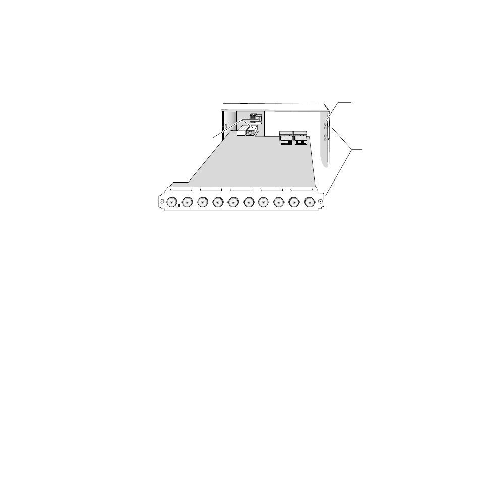
Install the 2041RDA rear module by inserting it into any rear slot
(1 through 12) of the frame as illustrated in
Figure 2. Installing the 2041RDA Rear Module
2.
Verify that the module connector seats properly against the midplane.
3.
Secure the module to the rear of the frame with the two screw locks on
either side of the back panel using a crossblade screwdriver.
Cabling
All cabling to the 2041RDA module is done on the connectors on the
module at the back of the 2000 frame. Refer to
detailed illustration of the rear connections referenced in the steps below.
Input
Connect an HD or SD video input to BNC J10. The 2041RDA module will
accept any of the serial digital component video signals conforming to the
following SMPTE formats:
•
SMPTE 292M
•
259M (143 Mbps, 177 Mbps, 270 Mbps, 360 Mbps)
•
4 Mbps to 1.5 Gbps (tested with PN20 pseudonoise sequence ratio,
maximum 19:1)
•
SMPTE 310M
•
DVB-ASI
Alignment post
and receptacle
Screw lock
(both sides)
8026_05
2000 frame (rear view)
Board edge guides
(both sides)
J10
J9
SIG
J8
J7
J6
J5
J4
J3
J2
J1
In
2041RDA