Rate led should be on. refer to – Grass Valley 2041RDA User Manual
Page 12
12
2041RDA Instruction Manual
Power Up
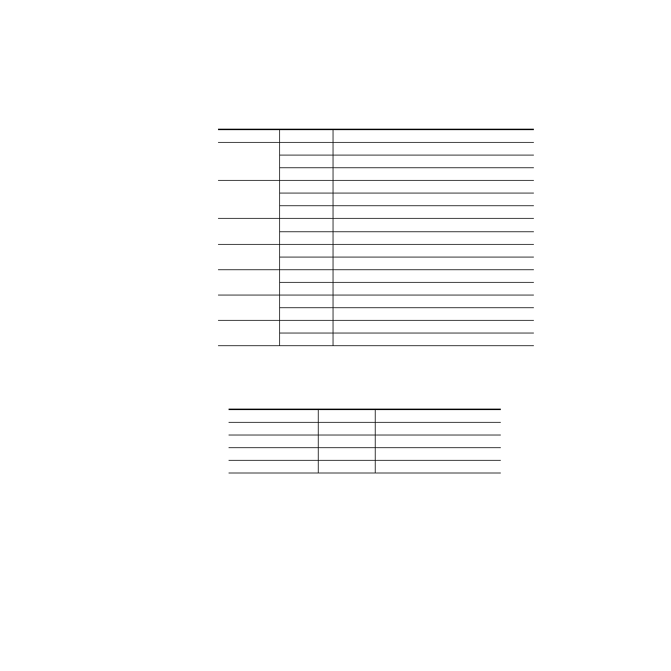
A red FAULT LED indicates an error situation and, when noted with the
other indicator LEDs, can indicate a specific problem area.
signal output and LED indications for the various input/reference combi-
nations and user settings.
provides the various output conditions possible for a given input
and module setting.
Table 1. Indicator LEDs and Conditions Indicated
LED
Indication
Condition
Off
Normal operation
FAULT (red)
On continuously
Module has detected internal fault
Long flash
Configuration problems, check inputs and settings
COMM (yellow)
Off
No activity on frame communication bus
Long flash
Location Command received by the module from a remote control system
Short flash
Activity present on the frame communication bus
CONF (yellow)
Off
Module is in normal operating mode
On continuously
Module is initializing, changing operating modes or updating firmware
PWR (green)
Off
No power to module or module’s DC/DC converter failed
On continuously
Normal operation, module is powered
REMOVR (yellow)
Off
Module settings match those indicated by module jumpers
On
Settings on the modules jumpers are overridden by remote control
SIG_PRES
LEDs (green)
Off
No input signal detected
On
Input carrier signal detected
RECLOCK
(yellow)
Off
Reclocking enabled and auto-rate detection mode is active
On
Bypass mode, input signal will not be reclocked
Table 2. Possible Output Conditions
Input
Setting
Output Condition
Standard Definition SDI video
Auto or Bypass
Standard Definition SDI video
High Definition SDI video
Auto or Bypass
High Definition SDI video
Other carrier
Auto or Bypass
Other carrier
No signal or over EQ range
All modes
Muted