Kameleon 2000 fiber ready modules, Installation – Grass Valley SFP Optical Converters User Manual
Page 10
10
SFP Optical Converters—Installation Manual
Kameleon 2000 Fiber Ready Modules
Kameleon 2000 Fiber Ready Modules
This section describes the installation and cabling of the SFP fiber optic sub-
modules for the fiber ready modules in the Kameleon 2000 Series.
Installation
CAUTION The Fiber Optic submodule is static sensitive. Use static handling precautions
when installing or removing the submodule.
The SFP submodule installs in the connector cage on the rear module cor-
responding to the front module in the 2000 frame.
illustrates a rear
module using the 2040RDA-16FR as an example.
The submodule is hot-pluggable and may be installed or removed with
power applied to the main module. The submodule type is identified by
name on the label or can be identified by the direction of the two arrows on
the label (Rx-Rx, Tx-Tx, or Tx-Rx).
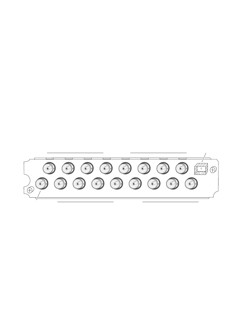
Figure 1. Rear Module Installation for 2040RDA-16FR
To install the optional SFP submodule, refer to
1.
Locate the cage connector on the top right of the rear module
corresponding to the front module.
2.
With the submodule handle in the up position, slide the metal casing,
label side up, into the cage connector on the rear module.
Note
When installed properly, the front end of the submodule will line up with the
BNCs. Do not try to force it in further.
J6
J7
J8
J9
2040
RDA-16
J5
J3
J4
J2
J1
J15
J16
J17
Input
J14
J12
J13
J11
J10
SFP Submodule
connector cage
8269_02
Outputs J1 – J8
Outputs J9 – J16