ARAG ORION Visual Flow User Manual
Page 5
5
Tab. 1
2.1
Electric connections
The Orion Visual Flow flowmeter has been designed to work as a separate device or to be connected
to ARAG appliances (computers, screens, displays) or to equipment by other manufacturers as
long as the latter is designed for use with flowmeters of this kind.
When used as a filling flowmeter, the flowmeter should ONLY be connected to ARAG
appliances.
ARAG is not liable for damage to the system, persons, animals or things caused by
incorrect or inadequate installation of the flowmeter.
In the event of damage to the flowmeter, caused by incorrect or unsuitable assembly,
any form of guarantee is automatically rendered null and void.
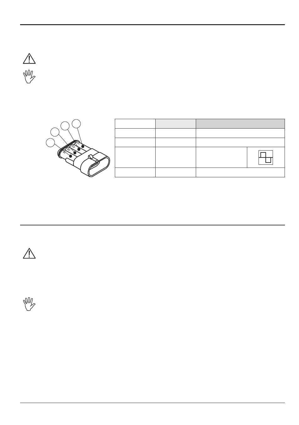
Connections of the flowmeter to devices not produced by ARAG are shown in Table 1.
Colour
Position
Connection
Black
1
GND
Red
2
+12 VDC
Green
3
Signal
(square wave)
Yellow
4
Pump control
It is possible to connect Orion Visual Flow to computers and screens in the Bravo series without the
"Pump Stop Kit" using the adapting cable (
code 4622BA50000.110), which enables the connection
between the 4-pole connector on the flowmeter and the 3-pole connector on the Bravo.
2.2
Hydraulic connections
For connection to the system, use appropriate fittings (Ref. ARAG General Catalogue).
Avoid bends and constrictions before connections and on tubes.
Regarding connections, use tubes and fittings properly sized for the operating pres-
sure of the system.
The tightening of hose tails should be made with special metal clamps ensuring
perfect sealing even at high pressures.
The connection by means of threaded fittings should be done taking operating pres-
sure into account.
CAUTION: For the implementation on already operating systems it is necessary to
follow all safety rules described herein.
System assembly and start-up must be carried out by expert personnel according to
the safety rules so as to ensure the same safety level of the system the flowmeter is
going to be installed in.
Tab. 1
Fig. 4
1
2
3
4
3
2
1
4