5 typical wiring diagram: jackscrew controls – AEC Colortronic MSH Series 2039 User Manual
Page 50
C Series Granulators
Appendix
50 of 53
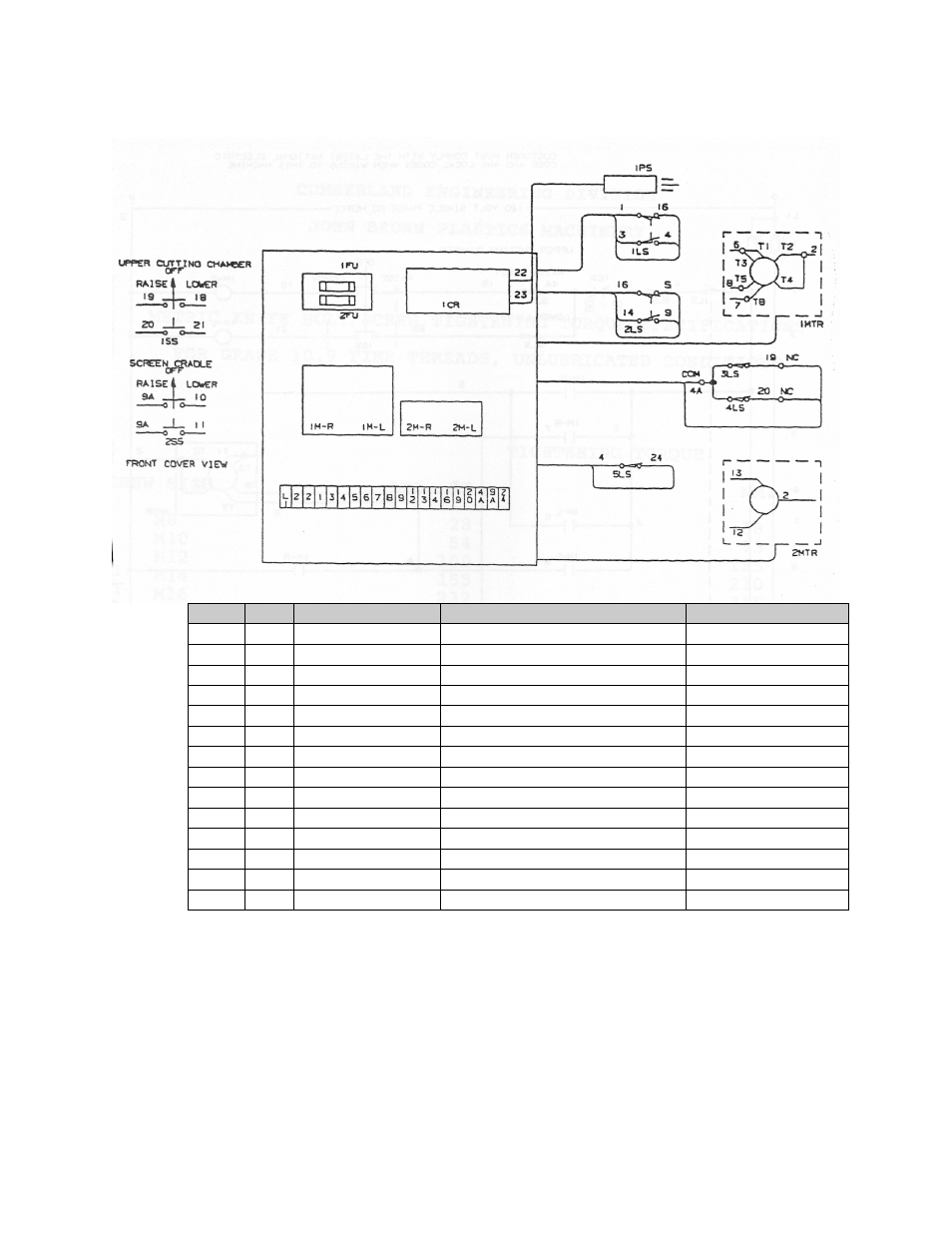
7-5 Typical Wiring Diagram: Jackscrew Controls
Item
Qty
Part Number
Description
Remarks
1
1
51-14126
Enclosure JIC 14 x 12 x 6
McKinstry
2
1
42-1412
Panel
McKinstry
1SS
1
10250T24115-T2
Switch, rev. Rotopush 3 position
Cutler-Hammer
2SS
1
10250T24115-T2
Switch, rev. Rotopush 3 position
Cutler-Hammer
1FU
1
FRN-12
Fuse-500 V, 12 Amp
Bussmann
2FU
1
FRN-25
Fuse-500 V, 25 Amp
Bussmann
3
1
H25030-2C
Block-Fuse, 2 pole-250 Volt
USD
4
20
525
Block – Terminal
Buchanan
5
1
530
End Barrier
Buchanan
1M
1
RLS14-A-O
Reversing Contactor –27 Amp
Cutler-Hammer
2M
1
RLS07-A-O
Reversing Contactor –10 Amp
Cutler-Hammer
6
2
TM36SPEC
Nameplates
Cutler-Hammer
1CR
1
S114166115
Amplifier – zero RPM
Electromatic
7
1
Socket Octal 11 pin
Idex
This manual is related to the following products: