3 drawings and diagrams, Figure 5: receiver wiring details, Vacuum hopper - time fill – AEC 1-Pump 1-Station Controller User Manual
Page 27: Switch as a bin full switch)
1 –Pump 1-Station Controller
Chapter 7: Appendix
26 of 30
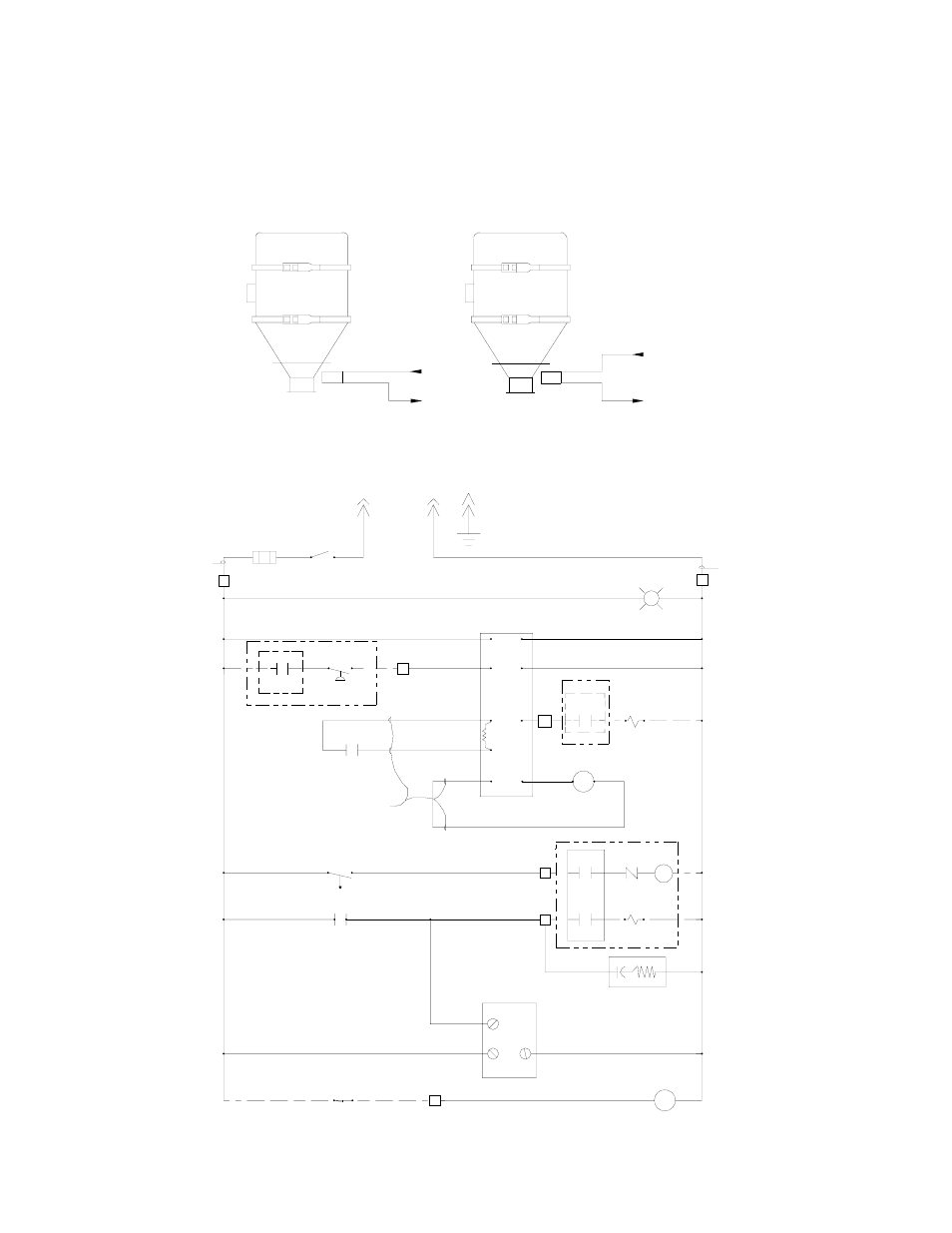
7-3 Drawings and Diagrams
Figure 5: Receiver Wiring Details
Vacuum hopper - Time Fill
Vacuum hopper - Time Fill
(when using the proximity
Bin-Full
switch
(1LS)
Brown
13
Blue
4 (115VAC)
To Bin-Full
control relay (2CR)
or selector switch
4 (115VAC)
13
To Bin-Full
control relay (2CR)
Bin-Full
switch
(1LS)
switch as a Bin Full switch)
Figure 6: Typical Single-Station Electrical Schematic without Optional Material Receiver Selector
Switch Circuit
18 ga
red (typical)
4
4
1FU
1A
3
1S
1
L1
115 VAC
2
L2
GRD
2
18 ga
white (typical)
2
Power On
G
1CNTL
2
2
2
2
2
2
2
2
Control board
Pump high
vacuum switch
Filter chamber
blowback solenoid
(or pump)
Vacuum
control
panel
Vacuum pump
motor starter
Vacuum pump
vacuum/vent
(or vacuum)
solenoid
Pump shutdown
timer (OFF-DELAY)
(0-30 sec.)
Bin Full
control relay
2CR
L3
1DISC-2
1M
10L
1DISC-3
1SOL
11
12
.5 MF SUP
1TMR
12
5
2 3
N. O.
1LS
13
4
4
4
4
4
4
12
1CR
1 2
1TMR
9
8
N. O.
11
8
9
1CR
8
3
4
9
7
1
4
5
2
3
10
6
8
8V
MOV
2SOL
1DISC-4
8
18 ga
blue
15
14
15 2CR 7
1VS
N. O.
1DISC-1