Mnr-310 system administrator ’s manual – ACTi MNR-310 User Manual
Page 30
MNR-310 System Administrator
’s Manual
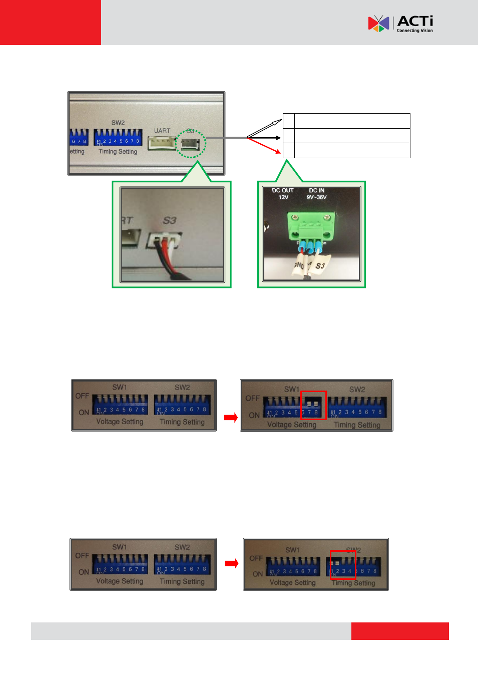
Connect the module
’s S3 control port to the MNR 310’s power ignition with the S3-to-Power
Ignition Port Cable by referring to the wiring definition and illustration below:
Step 4: Adjust voltage setting to be suitable for your environment.
Refer to the
“NISKIG120 Quick Reference Guide” provided with your power ignition control
module for your settings. An example is provided below.
For environments with 12V DC input and 12DC output, adjust your power ignition control
module
’s SW1 #7 and #8 to “ON”, as pictured below:
Step 4: Adjust power on/off delay timer to your desired settings
Refer to the
“NISKIG120 Quick Reference Guide” provided with your power ignition control
module for your settings. An example is provided below.
To achieve a delay of 10 seconds before powering on and a delay of 20 seconds before
powering off, adjust your power ignition control module
’s SW2 # 1 and #2 to “ON”, as pictured
below:
1 SLP_S3 IN (Input)
2 GND
3 Power ON Button (Output)
Settings for 12V DC input, 12V DC output
Settings for power on delay (10 sec), power off delay (20 sec)