Appendix – Edimax Technology Edimax 24 10/100TX + 2 10/100/1000T/Mini-GBIC Combo Web Smart Switch ES-5226RS User Manual
Page 56
50
Appendix
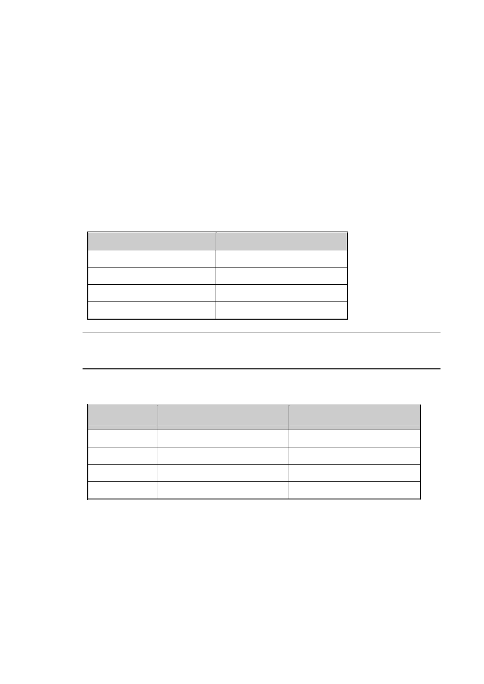
10 /100BASE-TX Pin outs
With10/100BASE-TX cable, pins 1 and 2 are used for transmitting data, and pins
3 and 6 for receiving data.
RJ-45 Pin Assignments
Pin Number
Assignment
1 Tx+
2 Tx-
3 Rx+
6 Rx-
[NOTE] “+” and “-” signs represent the polarity of the wires that make up each
wire pair.
The table below shows the 10 / 100BASE-TX MDI and MDI-X port pin outs.
Pin MDI-X
Signal Name
MDI Signal Name
1
Receive Data plus (RD+)
Transmit Data plus (TD+)
2
Receive Data minus (RD-)
Transmit Data minus (TD-)
3
Transmit Data plus (TD+)
Receive Data plus (RD+)
6
Transmit Data minus (TD-)
Receive Data minus (RD-)
10/100Base-TX Cable Schematic
The following two figures show the 10/100Base-TX cable schematic.
See also other documents in the category Edimax Technology Computer Accessories:
- ES-5224RFM (98 pages)
- ES-3124RE+ (29 pages)
- ES-5224RM EN (265 pages)
- ES-3124RL (41 pages)
- EK-08RO (17 pages)
- ER-5390S (12 pages)
- Edimax ES-3105P (40 pages)
- IC-1500WG (11 pages)
- IC-1500WG (41 pages)
- ES-5240G+ (111 pages)
- Two-console 8 port PS/2 KVM Switch (20 pages)
- Edimax EU-HB4S (2 pages)
- ER-5398S (13 pages)
- IC-1500WG (16 pages)
- IC-1500WG (2 pages)
- AR-7186WnB (92 pages)
- EW-7608Pg (8 pages)
- EW-7608Pg (1 page)
- EW-7303 APn V2 (18 pages)
- EW-7303 APn V2 (71 pages)
- EW-7733UnD (56 pages)
- ES-3316P (8 pages)
- BR-6258n (138 pages)
- EK-PS2C (2 pages)
- BR-6204Wg (91 pages)
- BR-6428nS (127 pages)
- NS-2502 (62 pages)
- EW-7612PIn V2 (52 pages)
- BR-6424n (161 pages)
- EW-7622UMn (47 pages)
- IC-7110W (172 pages)
- EW-7228APn (91 pages)
- IC-3100W (147 pages)
- PS-3103P (111 pages)
- HP-2001AV (21 pages)
- BR-6574n (160 pages)
- EW-7209APg (44 pages)
- ER-1088 (97 pages)
- ER-1088 (2 pages)
- WP-S1100 (88 pages)
- HP-5101K (24 pages)
- HP-5101K (9 pages)
- BR-6214K (26 pages)
- BR-6214K (45 pages)