Power, Tp/ft-10, Status – Westermo LRW-102 User Manual
Page 16
16
6650-2260
PWR
CH 1
TD
FL L
RD
FL R
PKT
CH 2
CH 1
COM +V
A +VB COM
TX RX
LON
ST
A
TUS
N2 N1
L2 L1
LR
W
-100 Series
CH 2
TX RX
1
2
2
1
PWR
CH 1
TD
FL L
RD
FL R
PKT
CH 2
CH 1
COM +V
A +VB COM
TX RX
LON
ST
A
TUS
N2 N1
L2 L1
LR
W
-100 Series
CH 2
TX RX
1
2
2
1
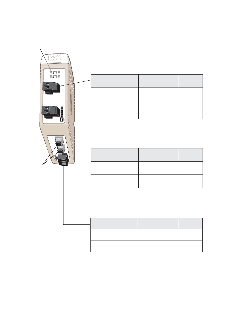
Location of Interface ports, LED’s and DIP-switches
Position
Direction*
Description
Product
marking
1
In
Common voltage
COM
2
In
Voltage A
+VA
3
In
Voltage B
+VB
4
In
Common voltage
COM
Power
LED Indicators(for details see page 17)
LRW-102/ LRW-102PP
Position
Direction*
Description
Product
marking
1
In/Out
TP/FT-10
connection
N1
2
In/Out
TP/FT-10
connection
N2
TP/FT-10
Position
Direction*
Description
Product
marking
1
In/Out
Contact with posi-
tion 2 when fibre
optical links are in
operation
1
2
In/Out
Common
2
Status
* Direction relative this unit
FX (Fibre)
Ch 1 and Ch 2.
(Ch 2 on
LRW-102 only)
For fibre details
see page 15.