3 communications, Lr-01 lr-01pp, Figure 3.2. ports on lr-01 – Westermo LR-01 User Manual
Page 8: Orks, Rx1 tx1 rx2 tx2 rx tx
8
6608-2201
3 COMMUNICATIONS
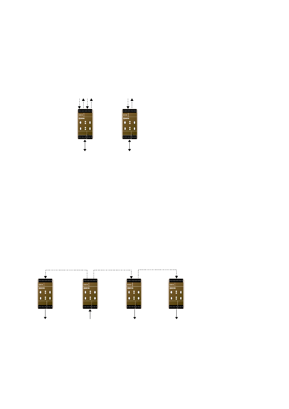
The LR-01 consists of either one (PP-version) or two sets of fibre optic ports, each with
its separate transmitter and receiver, and one L
ON
W
ORKS
®
FTT-10A transceiver for the
TP network. Figure 3.1 illustrates the communication ports on the LR-01.
If there are only two network segments that are to be connected, the point to point
version of LR-01 could be used. If the network contains of more than two segments,
the data needs to be retransmitted onto the fibre link to other connected network
segments.
The LR-01 with its two sets of fibre optic ports can then be used to build bus or ring
topology fibre links.
Figure 3.2 illustrates the general data flow when data is received from a TP segment.
Incoming data on a fibre link is transmitted onto the L
ON
W
ORKS
®
TP network as well as
forwarded to the next unit on the fibre link.
Figure 3.1. Ports on LR-01 and LR-01 PP (point to point)
Fibre Optic
TP Network
TP Network
Rx1
Tx1
Rx2
Tx2
Rx
Tx
LR-01
LR-01PP
N1 N2
L
N
LR-01
LONWORKS TP/FT-10
POWER
Rx1
Rx2
Tx1
Tx2
TD RD
C
E
PWR
OPTO LINK MONITOR
CH1
C
E
CH2
N1 N2
L
N
LR-01
LONWORKS TP/FT-10
POWER
Rx1
Rx2
Tx1
Tx2
TD RD
C
E
PWR
OPTO LINK MONITOR
CH1
C
E
CH2
Fibre
From TP Network
To TP Network
LR-01
LR-01
LR-01
To TP Network
LR-01
To TP Network
N1 N2
L
N
LR-01
LONWORKS TP/FT-10
POWER
Rx1
Rx2
Tx1
Tx2
TD RD
C
E
PWR
OPTO LINK MONITOR
CH1
C
E
CH2
N1 N2
L
N
LR-01
LONWORKS TP/FT-10
POWER
Rx1
Rx2
Tx1
Tx2
TD RD
C
E
PWR
OPTO LINK MONITOR
CH1
C
E
CH2
N1 N2
L
N
LR-01
LONWORKS TP/FT-10
POWER
Rx1
Rx2
Tx1
Tx2
TD RD
C
E
PWR
OPTO LINK MONITOR
CH1
C
E
CH2
N1 N2
L
N
LR-01
LONWORKS TP/FT-10
POWER
Rx1
Rx2
Tx1
Tx2
TD RD
C
E
PWR
OPTO LINK MONITOR
CH1
C
E
CH2
Figure 3.2. Ports on LR-01