Lr-01, Rx tx1 rx2 tx1 – Westermo LR-01 User Manual
Page 10
10
6608-2201
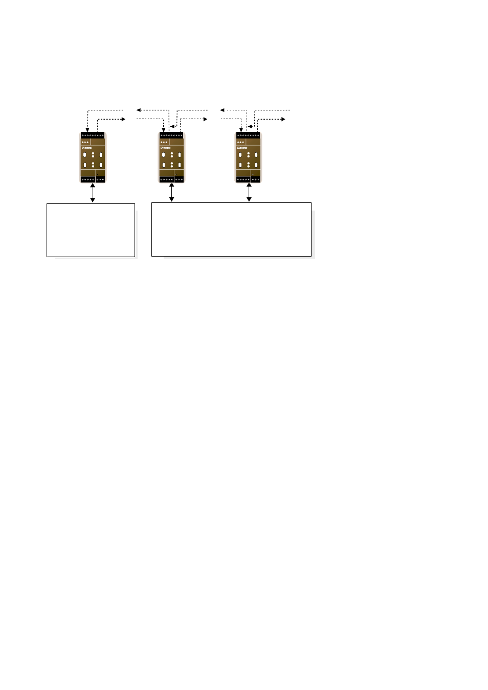
There is an additional mode that could be used to reduce network traffic between
different TP network segments. This mode is referred to as V-mode. The data flow
in V-mode is schematically illustrated in figure 3.5.
In this mode, data received on the Rx2 receiver is not transmitted onto the correspon-
ding TP segment. It is however forwarded to the next unit on the fibre link via Tx1.
Data received from a TP segment is transmitted only on Tx1. As shown in figure 3.4
only the first TP segment can send and receive data to and from all the other TP seg-
ments.
A single central management node could be placed in the main TP segment. With this
architecture, it could cycle around and do something to each node (such as network
management, polling etc.). Any background peer-to-peer activity or noise within other
TP segments would not be spread to other TP segments except the one containing the
central node.
Figure 3.5. Centralized communication architecture with isolated TP segments (V-mode)
LR-01
LR-01PP
Rx
Tx1
Rx2
Tx1
LR-01
Rx2
Tx1
Rx1
Tx2
Rx1
Tx2
This segment should
contain the central node.
If a LR-01 is used as
endpoint, the Rx1 must
be used.
Data from the TP segment is transmitted only
to the fiber link connected to Tx1.
Only data received from the Rx1 receiver is
transmitted out on the TP segment.
N1 N2
L
N
LR-01
LONWORKS TP/FT-10
POWER
Rx1
Rx2
Tx1
Tx2
TD RD
C
E
PWR
OPTO LINK MONITOR
CH1
C
E
CH2
N1 N2
L
N
LR-01
LONWORKS TP/FT-10
POWER
Rx1
Rx2
Tx1
Tx2
TD RD
C
E
PWR
OPTO LINK MONITOR
CH1
C
E
CH2
N1 N2
L
N
LR-01
LONWORKS TP/FT-10
POWER
Rx1
Rx2
Tx1
Tx2
TD RD
C
E
PWR
OPTO LINK MONITOR
CH1
C
E
CH2