Figure 2.3 network topologies, Orks – Westermo LR-01 User Manual
Page 7
7
6608-2201
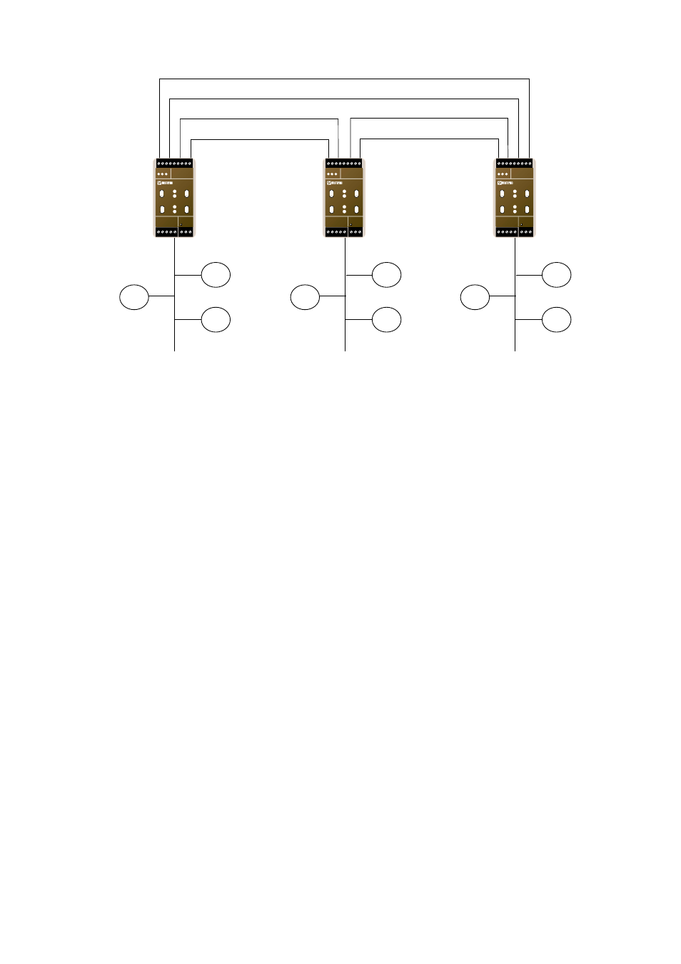
Fibre optic redundant link
LR-01
Ring master
LR-01
LR-01
TP Network
TP Network
TP Network
N1 N2
L
N
LR-01
LONWORKS TP/FT-10
POWER
Rx1
Rx2
Tx1
Tx2
TD RD
C
E
PWR
OPTO LINK MONITOR
CH1
C
E
CH2
N1 N2
L
N
LR-01
LONWORKS TP/FT-10
POWER
Rx1
Rx2
Tx1
Tx2
TD RD
C
E
PWR
OPTO LINK MONITOR
CH1
C
E
CH2
N1 N2
L
N
LR-01
LONWORKS TP/FT-10
POWER
Rx1
Rx2
Tx1
Tx2
TD RD
C
E
PWR
OPTO LINK MONITOR
CH1
C
E
CH2
Figure 2.3 Network topologies
In a fibre ring, one of the LR-01 units will be assigned as a ring master and then having
the responsibility to stop messages from looping around the ring. The LR-01 has a built-
in redundancy scheme that provides for fault tolerance in the fibre rings.
There is a maximum transmission distance on the fibre link depending on the available
power budget of the LR-01 units and losses due to attenuation in cables, connectors and
splice joints. With single mode fibre, distances up to 25 km can be reached.
In addition to the physical limitation there will also be a logical protocol specific limita-
tion that needs to be considered. The extension of the TP/FT network over a fibre optic
channel will impose a certain propagation delay across the network segments. Imposing a
propagation delay on a standard FT-10 channel will affect the Layer 1 timing and the
over-all channel media access. Significant propagation delay could result in packet colli-
sions and packet re-transmission, and thus network performance will decrease.
As always, it is recommended to analyse the network under worst-case condition using
a L
ON
W
ORKS
®
protocol analyser. This is even more important if very long fibre cables
are used with many segments and many nodes. To increase performance and distance
further, the 1 250 kbit/s LR-11 router is recommended. Please see section 3.4 further
discussions and recommendation regarding this issue.