Figure 3.6. ring communication – Westermo LR-01 User Manual
Page 11
11
6608-2201
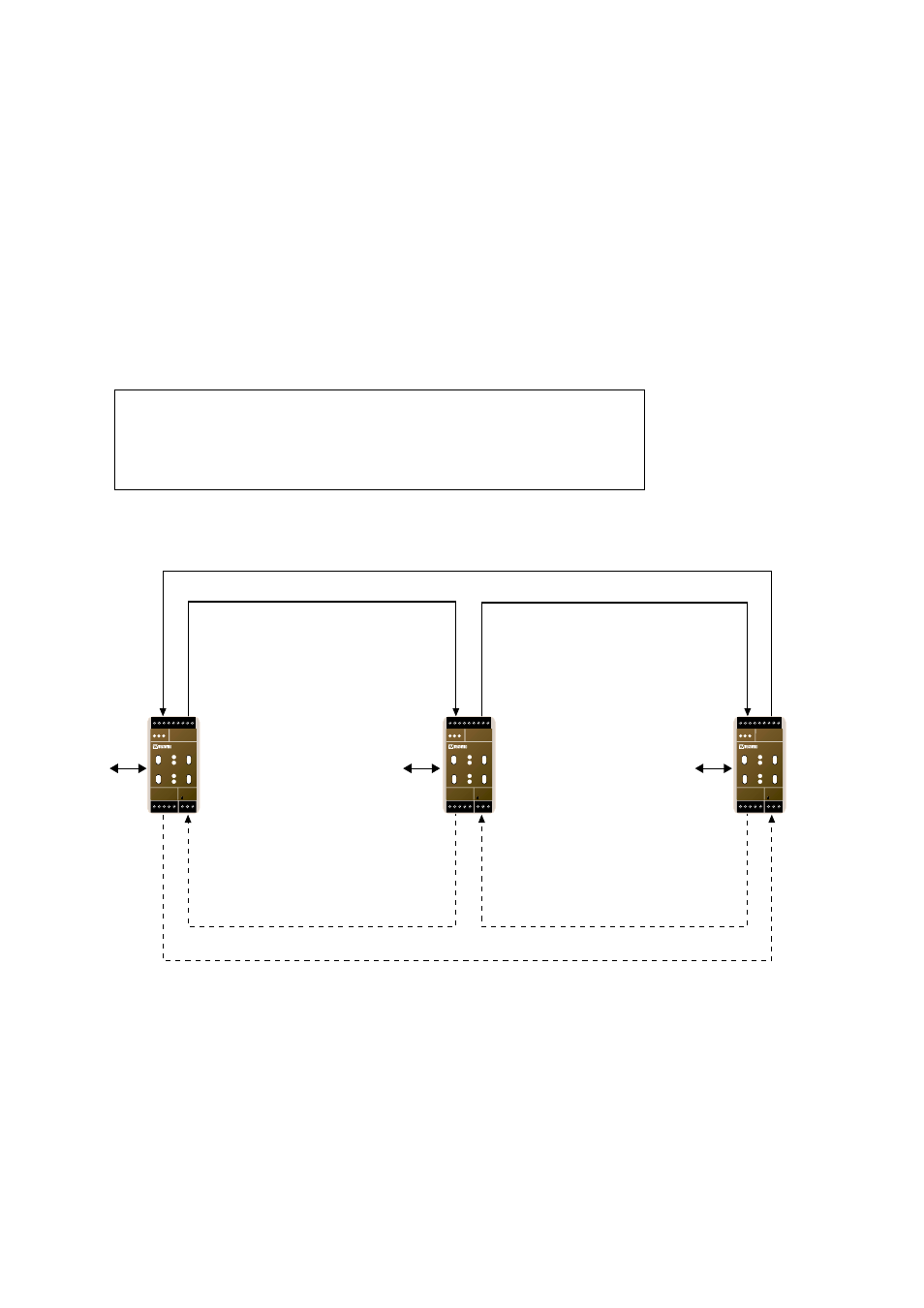
Figure 3.6. Ring communication
Figure 3.6 illustrates schematically how the fibre links are connected to form two rings.
3.3 Ring topology
The LR-01 units could be linked together to form a fibre optic ring. The ring topology
requires one dedicated LR-01 unit (ring master) to stop all messages on the fibre ring,
thus preventing message looping.
With ring topology, a built-in redundancy scheme offers communication fault tolerance. If
a fault is detected on one of the fibre links, the data flow will automatically be re-routed
to make a new communication path that reaches all units in the ring. The time to set-up
the new communication path could take up to 4 ms. Any data that is transmitted during
that time may be lost. The LR-01 can handle a fault on one fibre or a fibre pair, and still
be able re-route the communication. The LR-01 unit has two alarm outputs for fault
detection, one for each fibre link.
The redundancy scheme requires the fibre optic links to be connected as follow:
F/O Link 1: Tx2 " Rx1 " Tx2 " Rx1 " Tx2 etc.
F/O Link 2: Tx1 " Rx2 " Tx1 " Rx2 " Tx1 etc.
Rx2
TP Network
TP Network
TP Network
Tx1
Rx2
Tx1
Rx2
Tx1
Tx2
Rx1
Tx2
Rx1
Tx2
Rx1
LR-01
LR-01 Ringmaster
LR-01
N1 N2
L
N
LR-01
LONWORKS TP/FT-10
POWER
Rx1
Rx2
Tx1
Tx2
TD RD
C
E
PWR
OPTO LINK MONITOR
CH1
C
E
CH2
N1 N2
L
N
LR-01
LONWORKS TP/FT-10
POWER
Rx1
Rx2
Tx1
Tx2
TD RD
C
E
PWR
OPTO LINK MONITOR
CH1
C
E
CH2
N1 N2
L
N
LR-01
LONWORKS TP/FT-10
POWER
Rx1
Rx2
Tx1
Tx2
TD RD
C
E
PWR
OPTO LINK MONITOR
CH1
C
E
CH2