Westermo LD-64 User Manual
Page 15
15
6073-2002
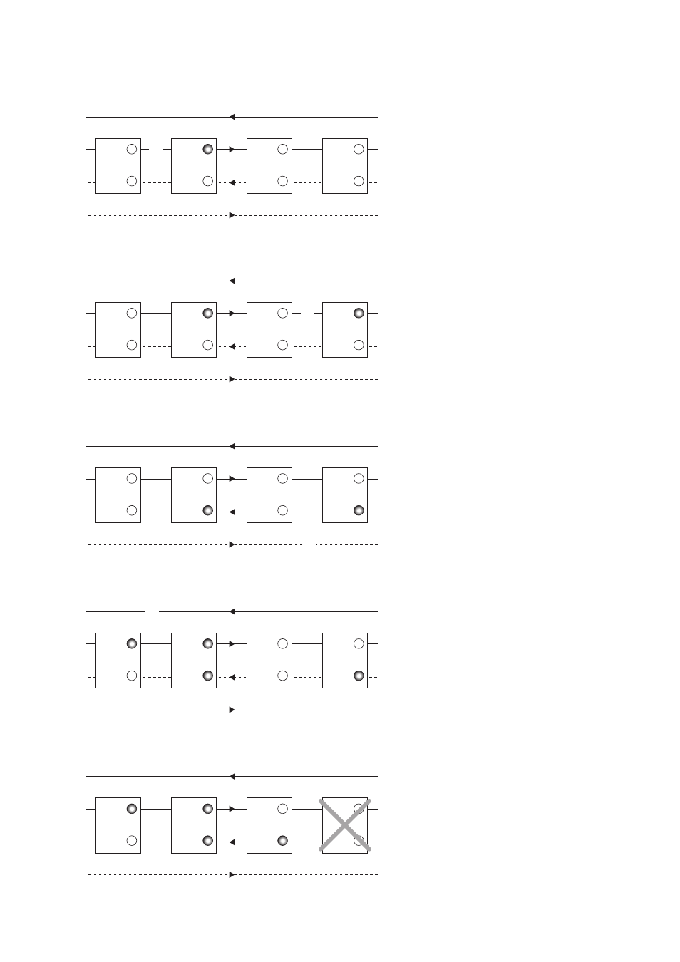
Below follows a number of different fault situations which shows the different alarm
outputs.
The receiver Rx2 at the master modem
detects an interruption on ring 1. Alarm
output CE1 indicates at the master unit.
The receiver Rx2 on slave modem 3
detects an interruption on ring 1. Alarm
signal CE1 indicates at slave modem 3
and also at the master unit.
Link 1
Link 2
CH1
CH2
CH1
CH2
CH1
CH2
CH1
CH2
x
LD-64 Slave 1
LD-64 Master
LD-64 Slave 2
LD-64 Slave 3
Link 1
Link 2
CH1
CH2
CH1
CH2
CH1
CH2
CH1
CH2
x
LD-64 Slave 1
LD-64 Master
LD-64 Slave 2
LD-64 Slave 3
The receiver Rx1 on slave modem 3
detects an interruption on ring 2. Alarm
signal CE2 indicates at slave modem 3
and also at the master unit.
Link 1
Link 2
CH1
CH2
CH1
CH2
CH1
CH2
CH1
CH2
x
LD-64 Slave 1
LD-64 Master
LD-64 Slave 2
LD-64 Slave 3
Slave modem 3 stops working due to
lack of power or other reason. Receiver
Rx2 on slave modem 1 and receiver Rx1
on slave modem 2 detects interruptions.
Alarm signal CE1 indicates on slave
modem 1 and CE2 indicates on slave
modem 2. Both CE1 and CE2 indicates
on master modem.
Link 1
Link 2
CH1
CH2
CH1
CH2
CH1
CH2
CH1
CH2
LD-64 Slave 1
LD-64 Master
LD-64 Slave 2
LD-64 Slave 3
The receiver Rx1 on slave modem 3 and
receiver Rx2 on slave modem 1 detects
interruptions. Alarm signal CE2 indicates
on slave modem 3 and CE1 indicates on
slave modem 1. Both CE1 and CE2
indicates at the master unit.
Link 1
Link 2
CH1
CH2
CH1
CH2
CH1
CH2
CH1
CH2
x
x
LD-64 Slave 1
LD-64 Master
LD-64 Slave 2
LD-64 Slave 3