Switch 1, Factory setting – Westermo FD-20 User Manual
Page 14
14
6630-2220
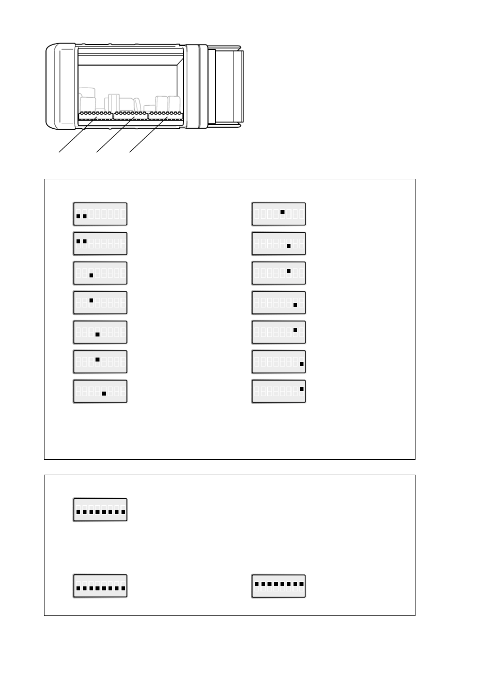
S3:1–8
S2:1–8
S1:1–8
Switch 1
ON
1 2 3 4 5 6 7 8
S1
No termination (RS-485)
ON
1 2 3 4 5 6 7 8
S1
Termination with fail-safe
(RS-485)
ON
1 2 3 4 5 6 7 8
S1
Data control
ON
1 2 3 4 5 6 7 8
S1
RTS/CTS control
ON
1 2 3 4 5 6 7 8
S1
RS-232 as serial
transfer port
ON
1 2 3 4 5 6 7 8
S1
RS-485 as serial
transfer port
ON
1 2 3 4 5 6 7 8
S1
2 ms turning time
Factory setting
ON
1 2 3 4 5 6 7 8
S1
No termination (RS-485)
Data control
RS-232 as serial transfer port
No turning time
5 s timeout allowed between received frames
No serial transfer at Stat_Diag (static diagnostics)
Reset slaves output data at running interrupt (RUN-LED off)
ON
1 2 3 4 5 6 7 8
S2
Default transfer setting
9 600 bit/s, 8 data bits,
no parity, 1 stop bit
ON
1 2 3 4 5 6 7 8
S3
Configuration mode, SyCon
®
* When this switch is selected, the slaves output remain at serial transfer interruption.To ensure that
the slaves output remain even at PROFIBUS DP interruption as well as power supply interruption or
restart of FD-20, select this switch together with selecting Controlled release of communication by the
application program in DP Master settings window (accessible from the Master Configuration window)
during the SyCon
®
configuration.
ON
1 2 3 4 5 6 7 8
S1
100 ms turning time
ON
1 2 3 4 5 6 7 8
S1
Timeout, 5 s allowed
between received frames
ON
1 2 3 4 5 6 7 8
S1
Timeout, 40 s allowed
between received frames
ON
1 2 3 4 5 6 7 8
S1
No serial transfer at
Stat_Diag (static diagnostics)
ON
1 2 3 4 5 6 7 8
S1
Serial transfer even
at Stat_Diag
(static diagnostics)
ON
1 2 3 4 5 6 7 8
S1
Stop the data exchange
with slaves at serial
transfer timeout
ON
1 2 3 4 5 6 7 8
S1
Continue the data exchange
with slaves at serial transfer
timeout*
NOTE
DIP-switch alterations are only
effective after a power on.