4 automatic control wiring, 5 automatic control wiring - 24 volt relay module, 6 automatic control wiring - 110 volt logic pump – Watson-Marlow Qdos30 Universal User Manual
Page 4: 1 optional input lead, 2 wiring up the terminal connectors, 3 24 volt relay module pcb connectors
EN
4
Watson-Marlow qdos30 pumps product safety information
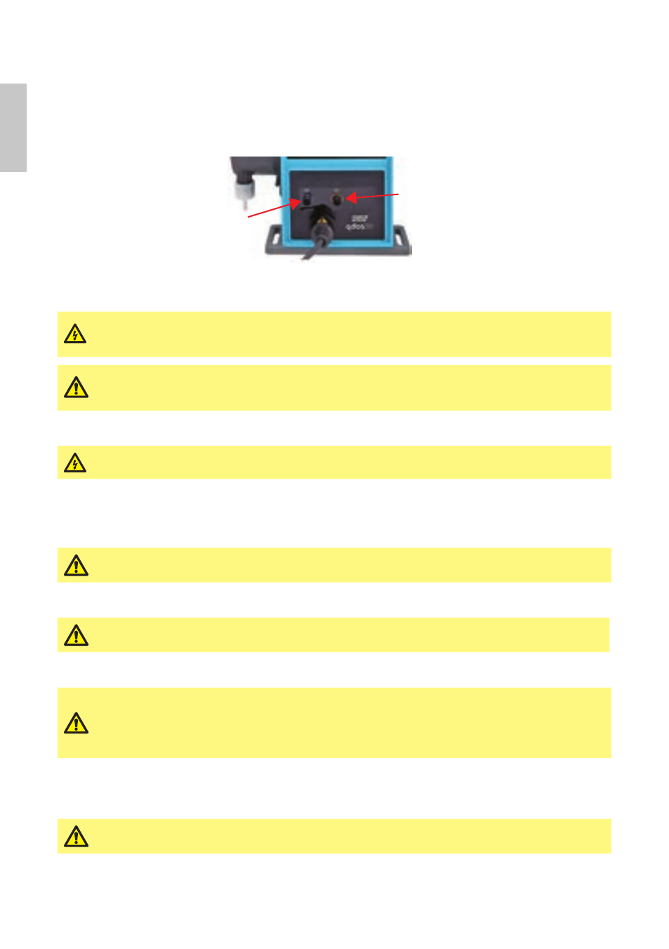
4 Automatic control wiring
Interfacing the pump with other devices is by means of two IP66 rated five pole M12 connectors mounted
on the front of the pump. M12 connectors with flying lead cables can be purchased as an accessory from
Watson-Marlow. The function of each of the leads is labelled.
Output
connection
Input
connection
It is the user’s responsibility to ensure the safe and reliable operation of the pump under remote and
automatic control.
Never apply mains power to the five pole M12 connectors. Apply the correct signals to
the pins, as shown below. Limit signals to the maximum values shown. Do not apply
voltage across other terminals. Permanent damage may result.
All input and output terminals are separated from mains circuits by reinforced
insulation. These terminals must only be connected to external circuits that are also
separated from mains voltages by reinforced insulation as a minimum requirement.
4.1
Optional input lead
Inverting the response is set up in software. Do not invert the polarity of the terminals.
If the polarity is inverted the motor will not run.
5 Automatic control wiring - 24 volt relay module
5.1
24 volt relay module: cover removal and refitting
Ensure that the 24 volt logic module cover is correctly secured at all times by all four
screws. Failure to do so may compromise the IP66 (NEMA 4X) protection.
5.2
Wiring up the terminal connectors
Ensure that unused openings on the module are sealed using the blanking plugs
provided. Failure to do so will result in loss of ingress protection.
5.3
24 volt relay module pcb connectors
Never apply mains power to the terminals within a qdos30 24V relay module. Apply
the correct signals to the terminals shown below. Limit signals to the maximum
values shown. Do not apply voltage across other terminals. Permanent damage, not
covered by warranty, may result. The maximum load on the relay contacts of this
pump is 24VDC at 1.0A. Note that the maximum switching capacity on DC is 30W.
6 Automatic control wiring - 110 volt logic pump
6.1
110 volt logic module: cover removal and refitting
Ensure that the 110 volt logic module cover is correctly secured at all times by all four
screws. Failure to do so may compromise the IP66 (NEMA 4X) protection.