Introduction, Indicators, Power – Verilink S Lite (34-00297.2) Product Manual User Manual
Page 15: Loop test, Tx data, Rx data, V.54 loop, Manual loop, Detect mode, 3 testing
3
T
ESTING
Introduction
This chapter describes the diagnostic and test features of the
Verilink S Lite. The unit is controlled manually using DIP
switches (the DIP switches are discussed on page 7).
Indicators
The unit indicators show power, loop status, and data activity.
Power
This green indicator shows that power is applied to the unit.
Loop Test
This indicator show the loop status of the unit. Amber indicates
the unit is in loop mode. When the indicator is Off, the unit is
not in loopback.
Tx Data
This green indicator shows the unit is transmitting data.
Rx Data
This green indicator shows the unit is receiving data.
V.54 Loop
This section describes loops that can be initiated on the S Lite.
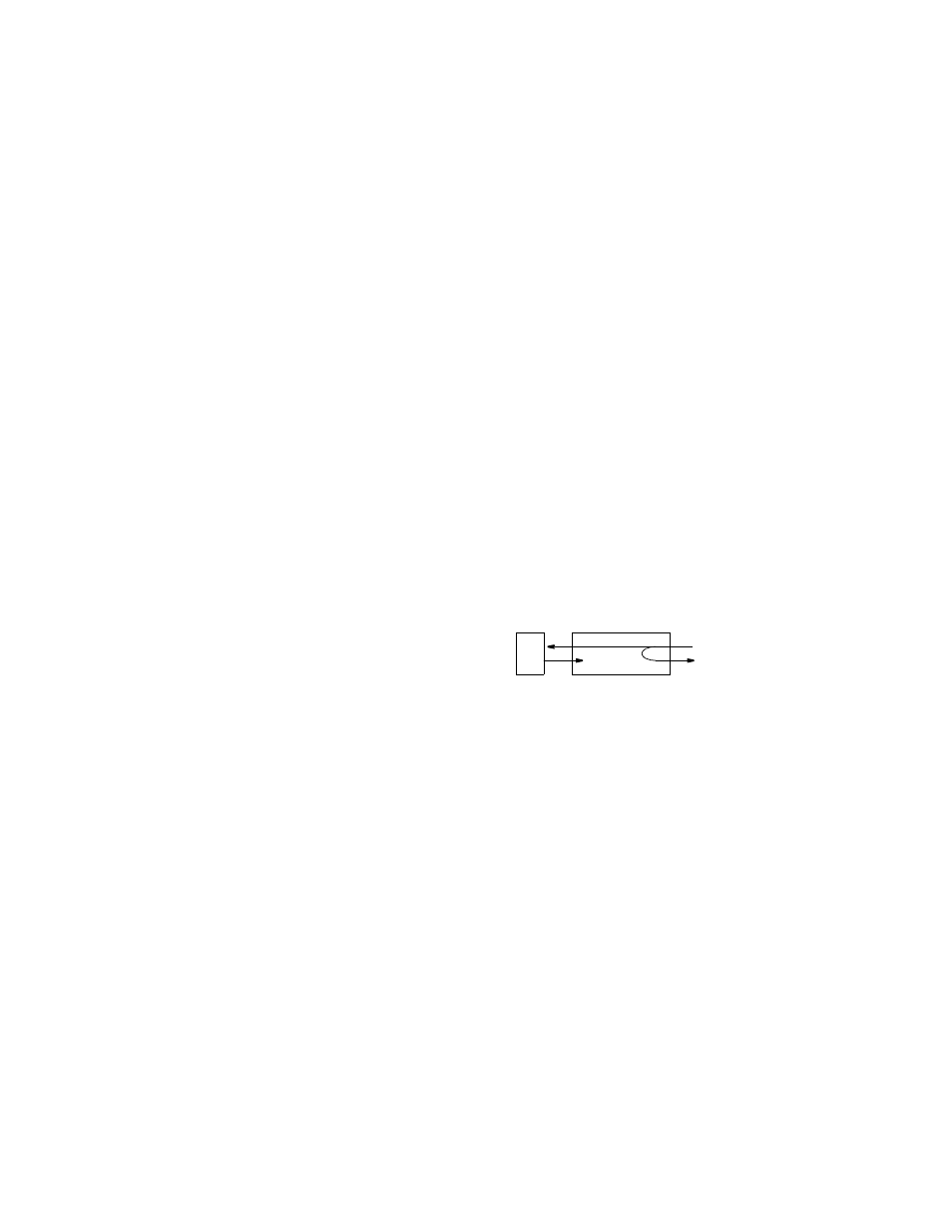
Manual Loop
This loop is activated by
setting DIP switch S1-1 to
the B position. This loop is
unidirectional and returns
the DCE receive data to the
DCE transmit data. The loop functions as shown in Figure 3-1.
Detect Mode
The unit is RDL compatible.
This loop is activated by the receipt of the V.54 loop command.
This loop is unidirectional and returns the DCE receive data to
the DCE transmit data. The loop functions as shown in
Figure 3-1.
The loop up code is 2048 ± 100 bits of V.54 loop-up pattern.
When this is detected, the unit is looped. The loop down code is
8192 ± 100 bits of V.54 loop-down pattern followed by 64 ones.
DTE
DCE
S Lite
Figure 3-1 V.54 Loop