Power, Configuration, Configuration switchs1 – Verilink S Lite (34-00297.2) Product Manual User Manual
Page 13: V.54 loop, Interface, Not used, Configuration switch s1, V.54 loop interface not used
Configuration 7
Power
Plug the connector from the power supply into the unit. Plug the
transformer into an appropriate outlet. This applies power to the
unit. Units require an AC IEC interconnect power cord.
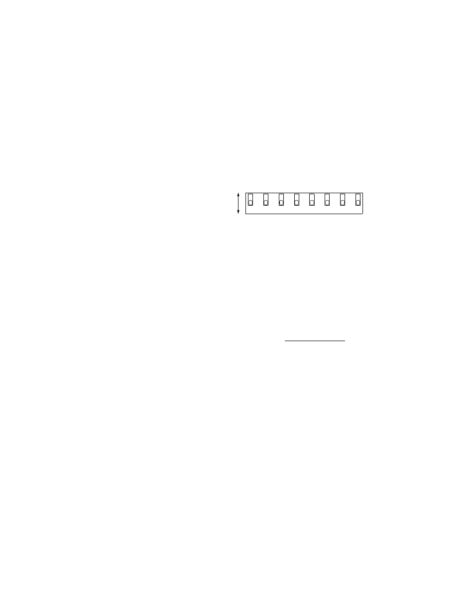
Configuration
This section
describes the
configuration
of the S Lite.
This unit is
configured
using DIP
switches S1.
Refer to
Figure 2-1 for
switch
locations.
Figure 2-1 Verilink S Lite Configuration Switches
Configuration
Switch S1
This switch provides the following configuration parameters.
V.54 Loop
Position 1 is used to set the unit to detect remotely initiated V.54
loop commands (A) or manually initiate a loopback (B). See page
9 for more information. The default is V.54 Loop Detect (A).
Interface
Positions 2, 3, 4, and 5 are used to select an interface (see
Figure 2-1).
Only one of these switches can be in position B at a time.
Disconnect the DCE and DTE cables from the unit before
selecting an interface.
Not Used
Positions 6, 7, and 8 are not used.
2
3
1
4
B
A
V
.54
L
o
o
p
Det
ect
X.
2
1
S
el
ect
ed
n
o
t se
le
ct
ed
n
o
t se
le
ct
ed
E
IA-5
3
0
S
el
ect
ed
5
8
6
7
no
t se
le
ct
ed
RS
-2
32
S
el
ect
ed
no
t use
d
no
t use
d
no
t use
d
no
t u
sed
no
t u
sed
no
t u
sed
n
o
t se
le
ct
ed
V
.54
M
anu
al
L
o
o
p
V
.35
S
el
ect
ed
S1
✍
✍